


Get started learning to build your own electronics by following our FREE online courses below!
Learn More »
Categories
- animatronics (12)
- apple (11)
- arduino (179)
- art (41)
- articles (121)
- artificial intelligence (11)
- automation (421)
- avr (205)
- bitcoin (3)
- breadboard (9)
- cameras (57)
- cars (26)
- cell phones (28)
- clothing mods (21)
- console mods (26)
- dangerous (94)
- desktop mods (24)
- embedded (5)
- flying things (54)
- fpga (22)
- gaming creations (108)
- interface (225)
- internet (17)
- laptop mods (6)
- lasers (22)
- linux (7)
- magnetic (3)
- medical (12)
- microcontrollers (51)
- misc projects (152)
- msp (12)
- music (124)
- pic (90)
- projects (23)
- pyroedu (76)
- raspberry pi (26)
- robots (312)
- security (36)
- sensors (307)
- software (200)
- solar (19)
- stamp (9)
- tools (149)
- tutorials (98)
- Uncategorized (45)
- usb (44)
- wireless (256)
Sponsors
Build Like A Pyro!
Find many of the parts used on this site at our favorite online electronics shop

Making a Web-Controlled Robotic Arm
Posted August 31, 2015 by Chris
"As part of Programmers’ Day celebration this year, Azoft web developers decided to surprise our fellow Azoft employees with a competition. To try something new and unusual, we created an internet-controlled robotic arm."
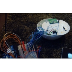
Remote Control Roomba From A Website Using Arduino
Posted August 25, 2015 by Chris
"Who has not wanted to vacuum when being away from home? The technique I use is a hack to take apart the remote control of the robot and connect it to an Arduino UNO. To control the Arduino from PC via USB, I use Messenger and lets Eventghost manage all communication with Serial-plugin."
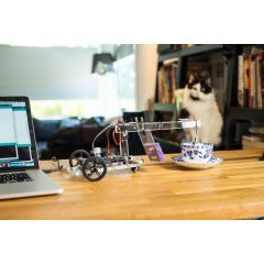
Penelope: Modulo’s tea brewing robot
Posted August 13, 2015 by Chris
"Meet Penelope, our tea brewing robot. Penelope brews the perfect cup of tea by monitoring the temperature of the water and steeping the tea bag for the best time suited for that type of tea. "
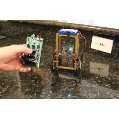
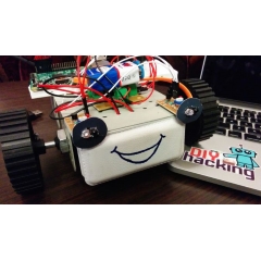
Farrel’s Balancing Robot
Posted August 10, 2015 by Chris
"Over a year ago I started to work on a small balancing robot. Between learning more about communication protocols and feedback loops I also had periods of schoolwork that kept me from this hobby. In the end my little robot was balancing on his own and I could send steering and throttle commands wirelessly."
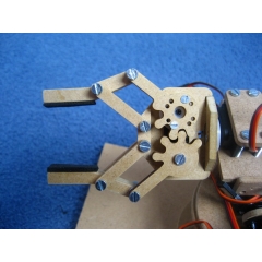
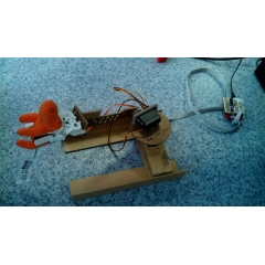
My Mini Servo Grippers And Robotic Arm
Posted July 29, 2015 by Chris
"A little time ago I made a robotic arm, without the gripper. So last week I draw a gripper that is compatible with a mini servo, I made two versions because I had to chose between two kinds of gears, straight and rounded. Because I first finished the straight gears version I milled this one first, but since there was a little play between the two gears I also made the second one, the one with the rounded gears."
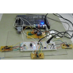
ECE5760 Robot Navigation Using Sound Localization
Posted July 16, 2015 by Chris
"The main idea behind this project was to construct a system on the Altera DE2 board that is capable of detecting the location of a sound source. We envisioned many purposes for such an instrument in gaming and other types of systems; however, to demonstrate our sound localizing capability in this project, we decided to use it for robot control."
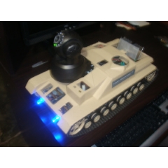
Remote Controlled Surveillance Mobile Robot with IP Cam
Posted July 14, 2015 by Chris
"The Senior Year Design Project was named Vanguard by the team. He is a remote controlled surveillance robot. To avoid data communication problems we decided to use different protocols for controlling the wireless camera and the robot. The robot can be controlled through desktop or laptop computers while the video can be controlled through internet, adhoc, WAN and LAN. It is powered by two batteries. One for the circuit and one for its motors."
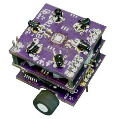
The GRITSBot
Posted July 11, 2015 by Chris
"The goal of the GRITSBot project is to make multi-agent experiments more accessible to the research community at large as well as to students of all age groups. In a further step, we intend to open up a show testbed to the general public."
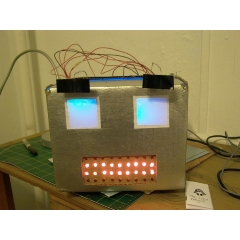
Build an Arduino-Powered Talking Robot Head
Posted June 8, 2015 by Chris
"This robot head was originally built as a end of the year project for my physical computing class, but over the summer it has ‘learned’ how to talk. The head is powered by two Freeduinos, 3 TLC5940NT chips and an Adafruit Industries Wave Shield. The head is currently connected to a computer by two USB cables, one for power, one for sending it serial commands on what to say/emote."
Build Raspberry Pi Robots – A Tutorial
Posted June 1, 2015 by Chris
"If you are a beginner to Raspberry Pi and were looking for a simple hardware project, then look no further. This tutorial will show you to develop a python based robot which avoids obstacles and navigates freely. Obstacle avoiding robots are fairly common and easy to make."
Currently Hot
DIY Mini PIC Development Board
build your own quick, easy and awesome pic dev board
Wireless XBee Pan/Tilt With Servos
build a wireless pan/tilt system for your camera
PIC Prototyping: MPLABX + PICKIT3 Intro
learn how to use mplabx with the new pickit3
FPGA to 16×2 LCD Interface (HD44780)
build a cpld to 16x2 lcd interface to display output
Using A Simple Tilt Sensor
learn how the most basic of tilt sensors works
Animatronics

Recent Articles
Arduino DDS Shield
build your own arduino based analog signal generator
A Digital Multimeter In Review (Tenma 72-7735)
learn about your typical digital multimeter in review
The PIC Annoy PCB
build something to annoy your co-workers
Automate Your Life With Cron
learn how to use cron for computer automation
Web Scraping For Weather Updates
learn how to use php to scrape the web
Creating A Web Server In Linux
learn how to make a lamp web server in linux
Stepper Motor Control With A stepRocker TMCM-1110
learn how a commercial stepper motor controller works
Arduino To PIC Wireless Proximity Motor Control
control a motor with a distance sensor wirelessly
PIC to Arduino Wireless Communication via XBee
use xbee to make a pic wirelessly talk to an arduino
Motor Control via Infrared Distance Sensor
control a motor simply by waving your hand

