


Get started learning to build your own electronics by following our FREE online courses below!
Learn More »
Categories
- animatronics (12)
- apple (11)
- arduino (179)
- art (41)
- articles (121)
- artificial intelligence (11)
- automation (421)
- avr (205)
- bitcoin (3)
- breadboard (9)
- cameras (57)
- cars (26)
- cell phones (28)
- clothing mods (21)
- console mods (26)
- dangerous (94)
- desktop mods (24)
- embedded (5)
- flying things (54)
- fpga (22)
- gaming creations (108)
- interface (225)
- internet (17)
- laptop mods (6)
- lasers (22)
- linux (7)
- magnetic (3)
- medical (12)
- microcontrollers (51)
- misc projects (152)
- msp (12)
- music (124)
- pic (90)
- projects (23)
- pyroedu (76)
- raspberry pi (26)
- robots (312)
- security (36)
- sensors (307)
- software (200)
- solar (19)
- stamp (9)
- tools (149)
- tutorials (98)
- Uncategorized (45)
- usb (44)
- wireless (256)
Sponsors
Build Like A Pyro!
Find many of the parts used on this site at our favorite online electronics shop

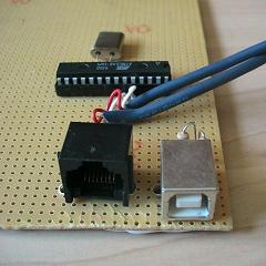
DIY USB Joystick
Posted March 17, 2008 by Chris
This project is extremely useful for you flight simulator gurus out there. Commercially available joysticks are never good enough for games that demand pinpoint accuracy. Find out how to mod your joystick or even create your very own.
2 Responses to “DIY USB Joystick”
Leave a Reply
Currently Hot
Wireless Motor Controller
easy wireless control of an led and a motor
Mini IR Theremin
make your own mini ir theremin
Intro to Xbee: Build A Xbee Wireless Interface
learn to use xbee for wireless communication
10 Amp H-Bridge For Motor Control
build your own beefy dc motor controller
Homemade Breakout Board PCBs
breadboard complex components easily
Animatronics
Recent Articles
Arduino DDS Shield
build your own arduino based analog signal generator
A Digital Multimeter In Review (Tenma 72-7735)
learn about your typical digital multimeter in review
The PIC Annoy PCB
build something to annoy your co-workers
Automate Your Life With Cron
learn how to use cron for computer automation
Web Scraping For Weather Updates
learn how to use php to scrape the web
Creating A Web Server In Linux
learn how to make a lamp web server in linux
Stepper Motor Control With A stepRocker TMCM-1110
learn how a commercial stepper motor controller works
Arduino To PIC Wireless Proximity Motor Control
control a motor with a distance sensor wirelessly
PIC to Arduino Wireless Communication via XBee
use xbee to make a pic wirelessly talk to an arduino
Motor Control via Infrared Distance Sensor
control a motor simply by waving your hand


November 5th, 2008 at 8:18 am
Hi, I was looking for a schematic diagram for a joystick and I bumped into your this design, and there is a couple of things that are not clear to me…
Im in my beginning phase of electronics, so please understand!!
1- in the diagram, pin number 7 of the ATMega 8 is a VCC, and pin number 20 reads VCC on 1 side and inside it reads AVCC. What should i connect in pin 7 and in pin 20??
2- one end of the resistor of 2,2k says VCC. where does this one goes??
3- both joined capacitor ends read VCC. where does it go??
4- pin number 1 read PC6, where does it go to?
5- If i wanted to build it with only 10 buttons, should i start removing from the diagram the smaller numbers like PD0 and PD 1 lines or the PD6 and 7??
6- Is the ISP port necessary if i don’t want to perform any special programming??
7- where does the ISP show on the schematic diagram??
Thank you so much in advance, I hope i don’t bother you with my questions…
Peace!!
Esteban Diaz
January 16th, 2009 at 11:32 pm
Can you share information about usb joystick?
thank you.