Add Arduino & LED Control
Since we just finished building one half the circuit, let's get started finishing it off by building the other half. If you look at the schematic again, the parts that we'll be putting together here are the remaining Arduino connections and the layer/cathode control with all the 2N2222 transistors.
Finishing The Circuit Off
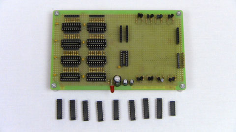
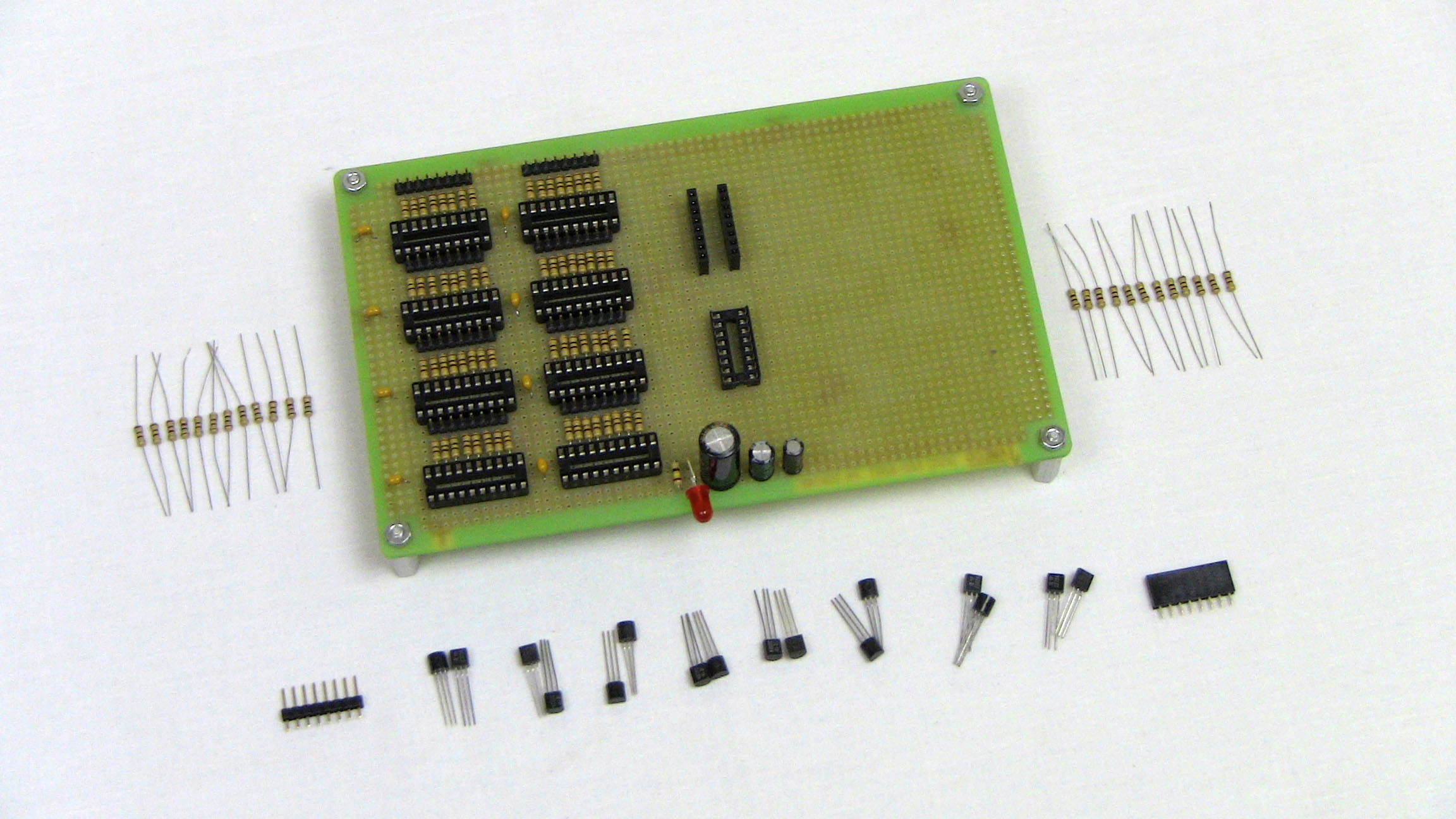
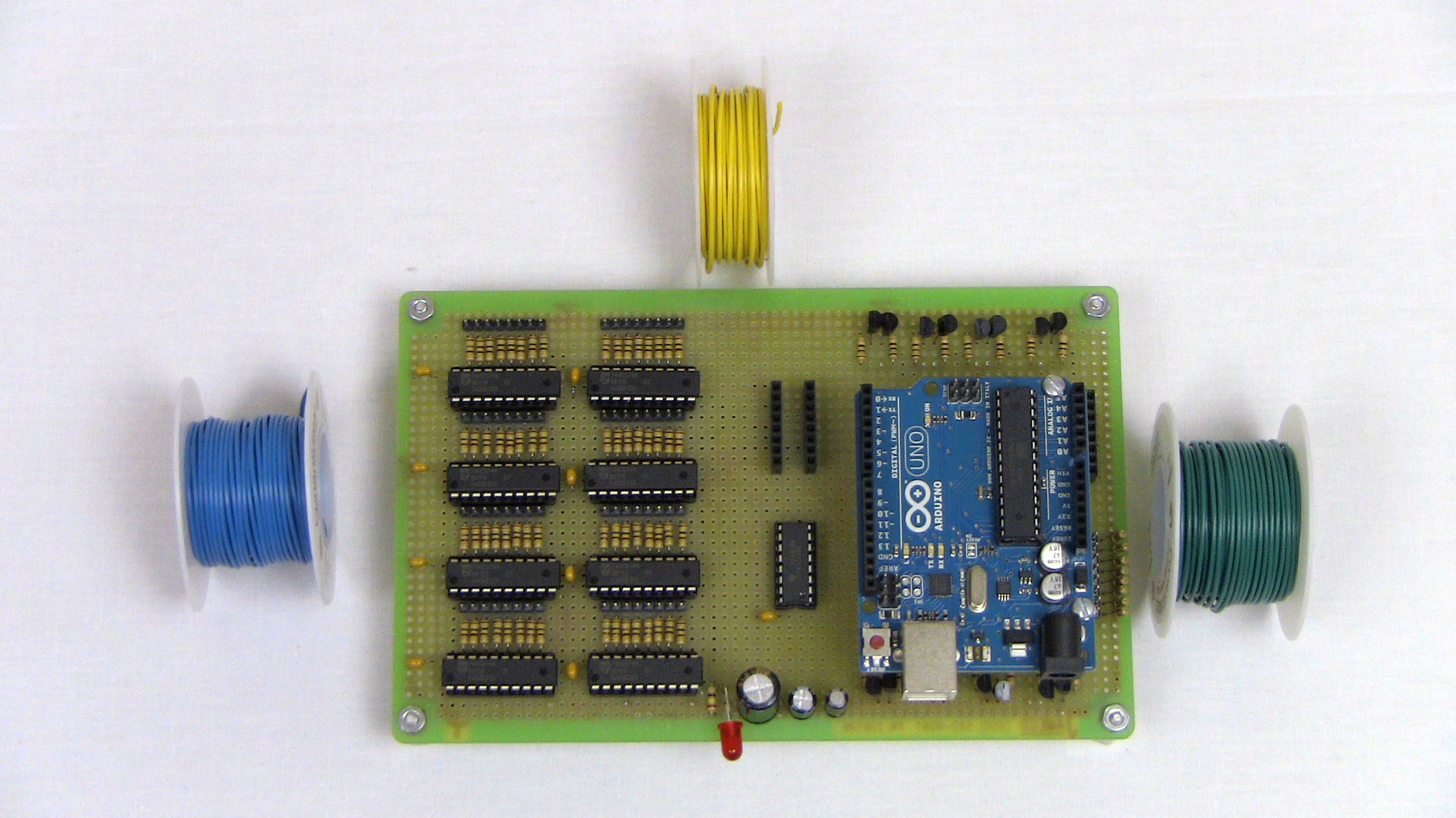
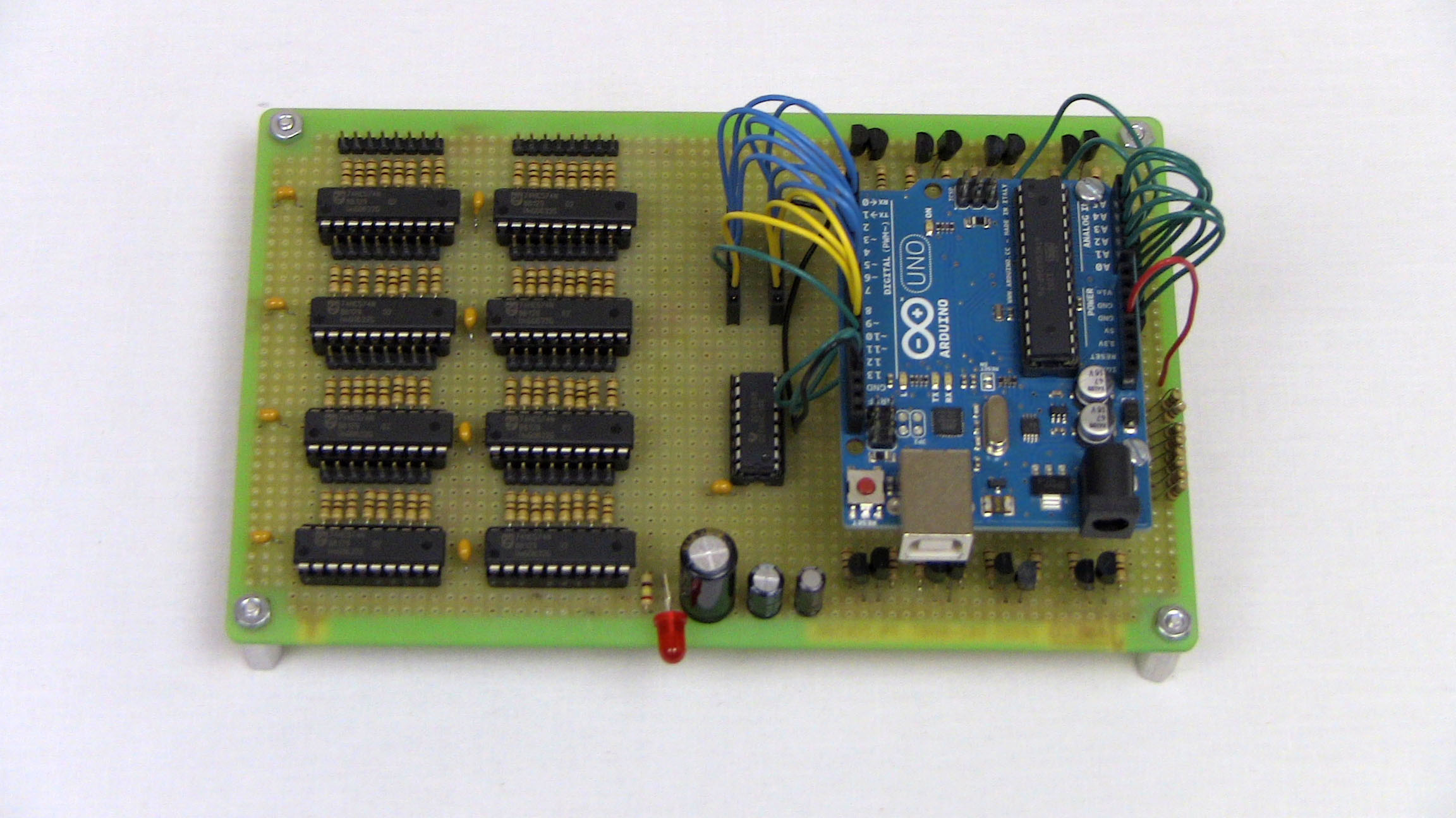
First we'll build the cathode code on the protoboard and then we'll add the Arduino interface to finish it off. All the parts needed to build the layer/cathode control can be seen below:
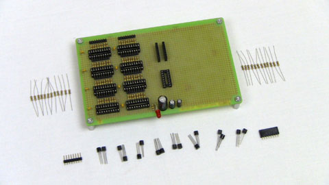
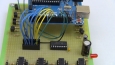
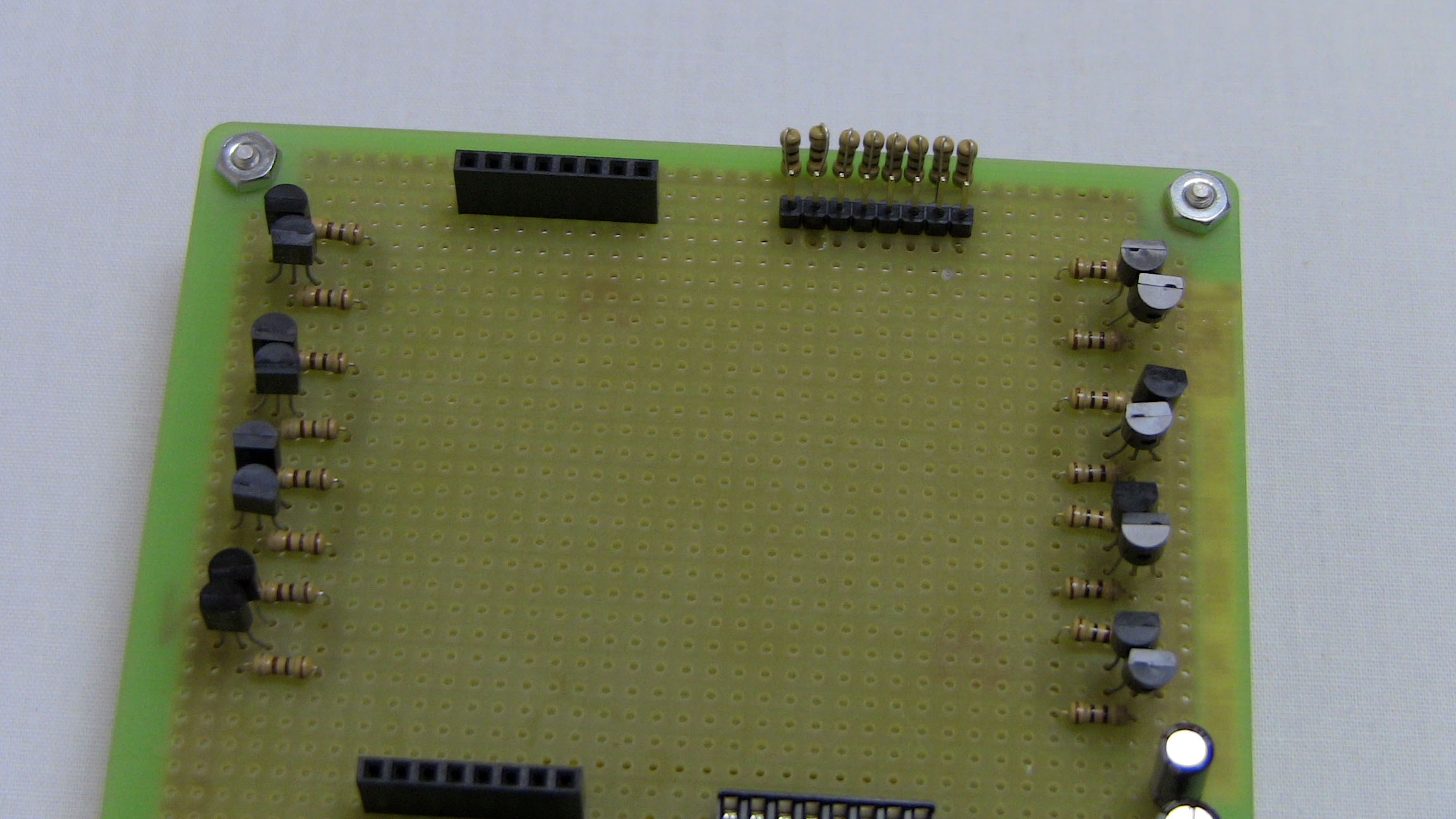
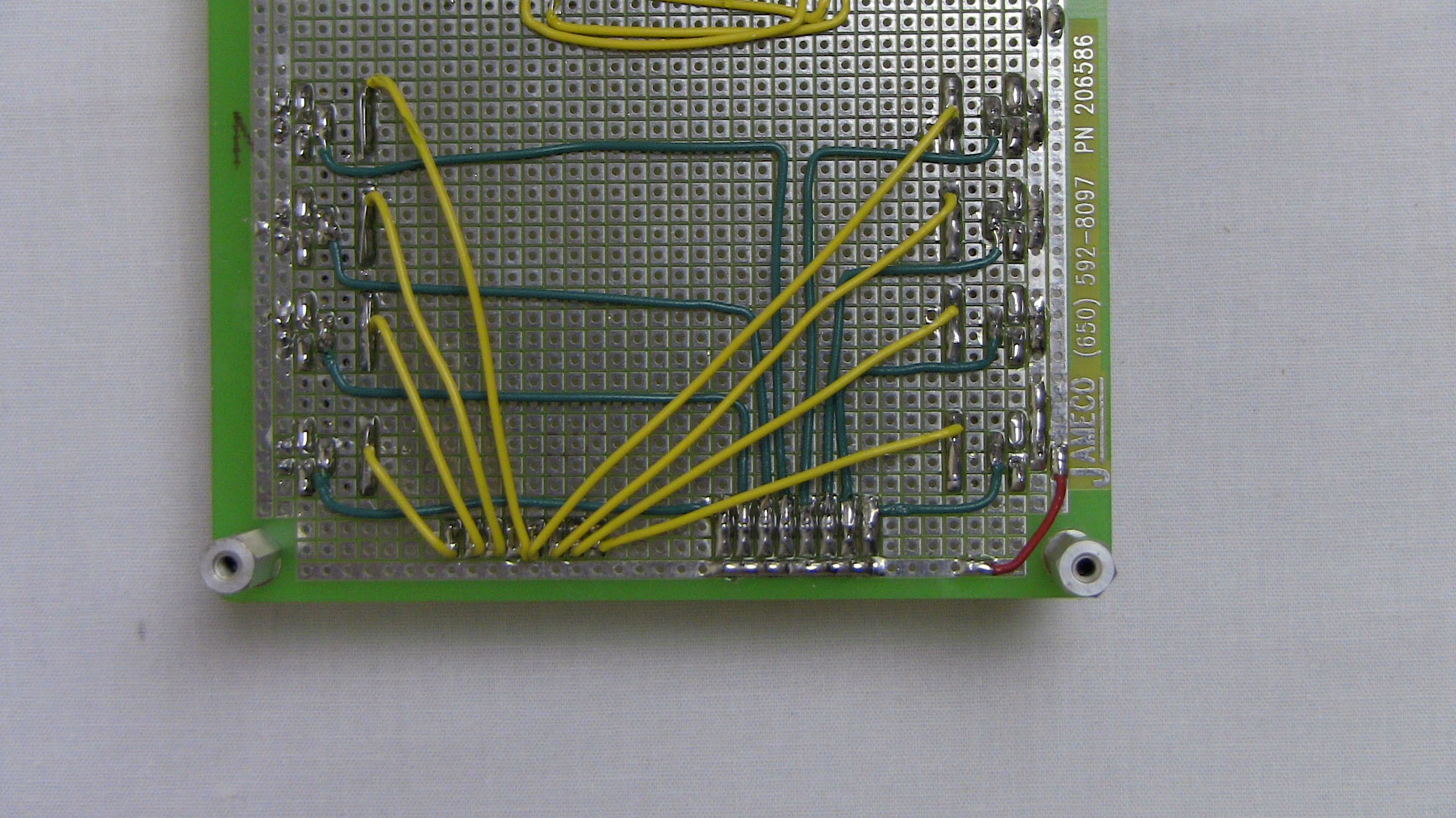
·The 16 transistors are soldered into place, their 100Ω resistors are connected to them and the two connection ports are added to the side of the board. The row of 8 resistors near the 8 pin header are pull-up resistors to help prevent LED ghosting.
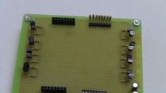
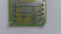
·8 wires (green) are used to connect the cathode control from the transistors to the 8 pin header and another 8 wires (yellow) are used to connect from the cathode control resistors to the 8 pin arduino interface connector.
·Now it's time to add your IC's into their respective sockets. It's hard to mess this part up, the 74HC574's are all 20 pin devices and the 74HC138 is a 16 pin device. So plug'm in! It helps to bend the pins on the ICs a little bit first, use a table or book to bend them inward all at once for each side of an IC. Then they will slide much more easily into the sockets.
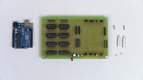
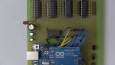
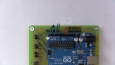
·Next up, add the Arduino to the board. You can see the obvious space in the middle of the board that I left for the Arduino. The Club Jameco kit included two standoff pins for the Arduino so we'll use them to make the Arduino stand above the protoboard.
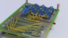
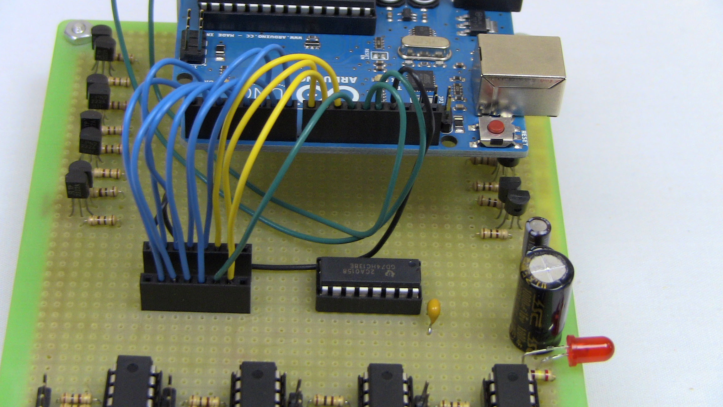
·This is it, the last step for building the circuit, I promise!. Gather some wire together (I like to use different colors to associate them with different functions) so that you can connect the Arduino to all of the circuitry on the board.

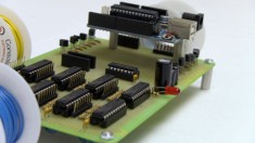
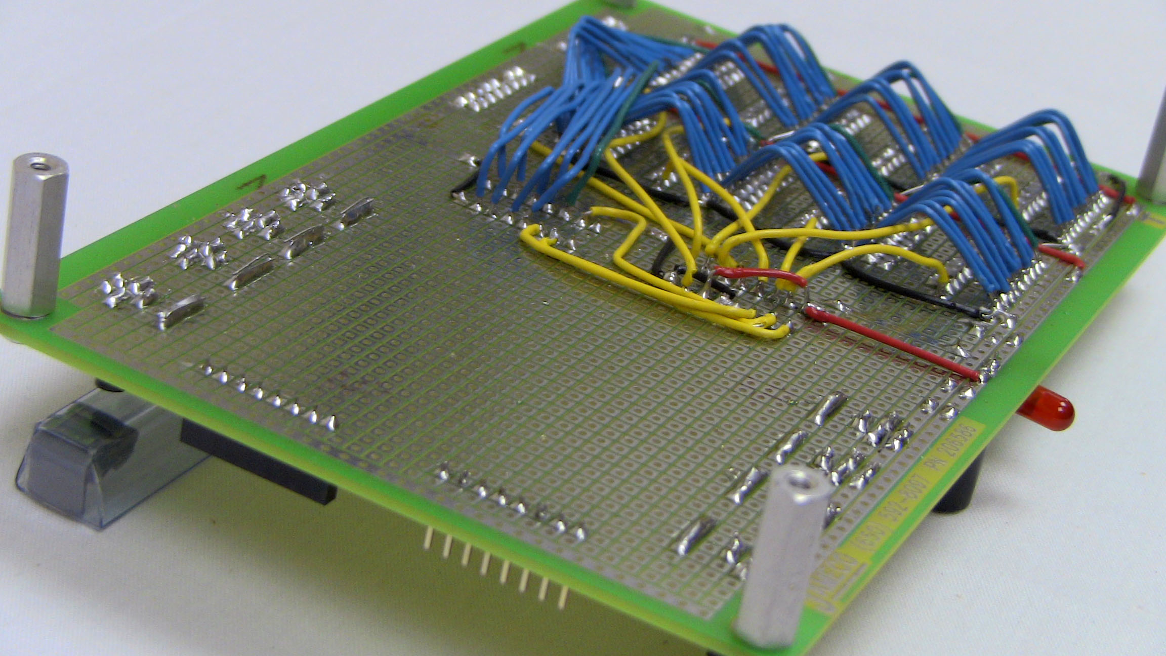
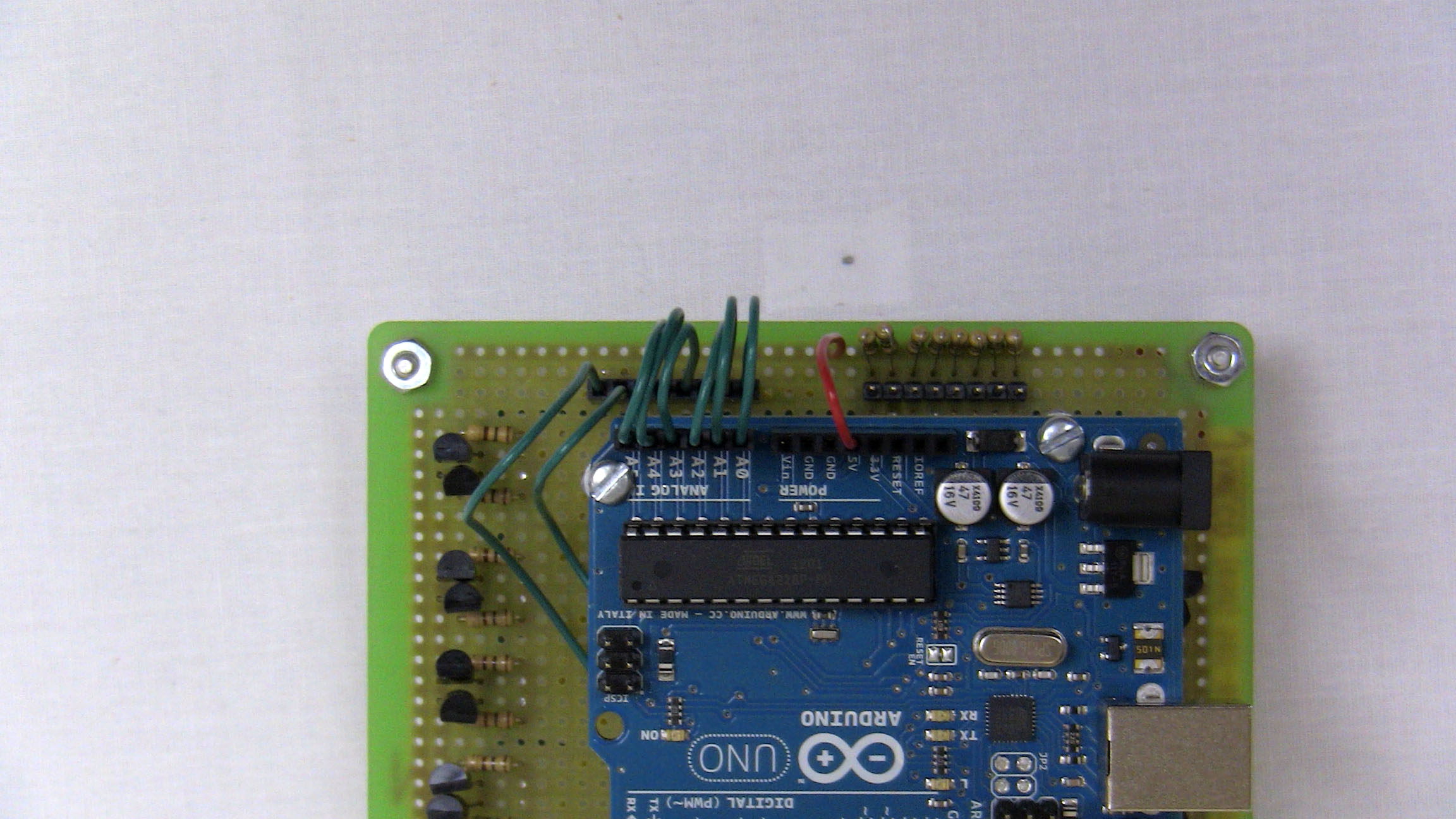
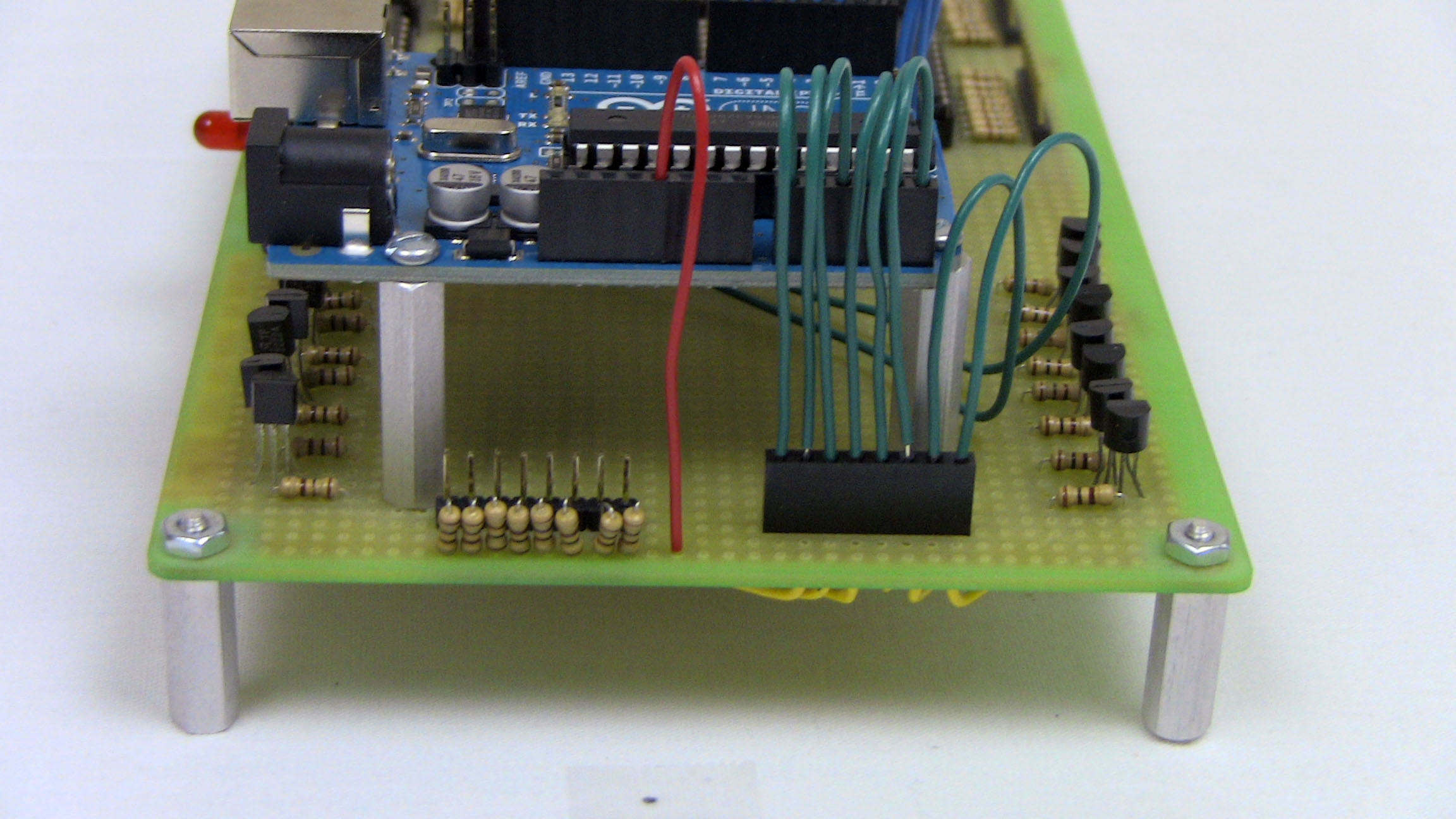
·To connect the Arduino to all the rest of the circuitry on the board, use the J1 and J2 connectors. Teal wires represent the cathode control, they all go to J2 on the side of the board. They are connected like so: AN0-AN5,D12,D13 map to Pin 0->7 on J1. J2, in the middle of the board is more complicated. Refer to the schematic to see the wiring for it. But generally, yellow wires to J2 are the address control, blue wires are the data bus and the teal wire is for the output control.
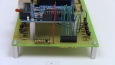
·Alright fine, one more thing to do. Connect the +5v pin of the Arduino to the +5v power bus on the protoboard (use a red wire please!). Do the same thing for ground from Arduino GND to the ground bus on the protoboard (use a black wire please!).

·So we're almost there, but we still need to connect the LED cube to our protoboard and so construction continues.....
Since we just finished building one half the circuit, let's get started finishing it off by building the other half. If you look at the schematic again, the parts that we'll be putting together here are the remaining Arduino connections and the layer/cathode control with all the 2N2222 transistors.
Finishing The Circuit Off
First we'll build the cathode code on the protoboard and then we'll add the Arduino interface to finish it off. All the parts needed to build the layer/cathode control can be seen below:
·The 16 transistors are soldered into place, their 100Ω resistors are connected to them and the two connection ports are added to the side of the board. The row of 8 resistors near the 8 pin header are pull-up resistors to help prevent LED ghosting.
·8 wires (green) are used to connect the cathode control from the transistors to the 8 pin header and another 8 wires (yellow) are used to connect from the cathode control resistors to the 8 pin arduino interface connector.
·Now it's time to add your IC's into their respective sockets. It's hard to mess this part up, the 74HC574's are all 20 pin devices and the 74HC138 is a 16 pin device. So plug'm in! It helps to bend the pins on the ICs a little bit first, use a table or book to bend them inward all at once for each side of an IC. Then they will slide much more easily into the sockets.

·Next up, add the Arduino to the board. You can see the obvious space in the middle of the board that I left for the Arduino. The Club Jameco kit included two standoff pins for the Arduino so we'll use them to make the Arduino stand above the protoboard.

·This is it, the last step for building the circuit, I promise!. Gather some wire together (I like to use different colors to associate them with different functions) so that you can connect the Arduino to all of the circuitry on the board.

·To connect the Arduino to all the rest of the circuitry on the board, use the J1 and J2 connectors. Teal wires represent the cathode control, they all go to J2 on the side of the board. They are connected like so: AN0-AN5,D12,D13 map to Pin 0->7 on J1. J2, in the middle of the board is more complicated. Refer to the schematic to see the wiring for it. But generally, yellow wires to J2 are the address control, blue wires are the data bus and the teal wire is for the output control.

·Alright fine, one more thing to do. Connect the +5v pin of the Arduino to the +5v power bus on the protoboard (use a red wire please!). Do the same thing for ground from Arduino GND to the ground bus on the protoboard (use a black wire please!).
·So we're almost there, but we still need to connect the LED cube to our protoboard and so construction continues.....