LED Cube Cable Assembly
At this point we've built the complete circuit and our LED cube. Now we need to build up some cables and connect them up to the LED cube so our LED drive board can work its magic. So let's do it!
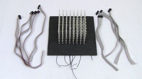
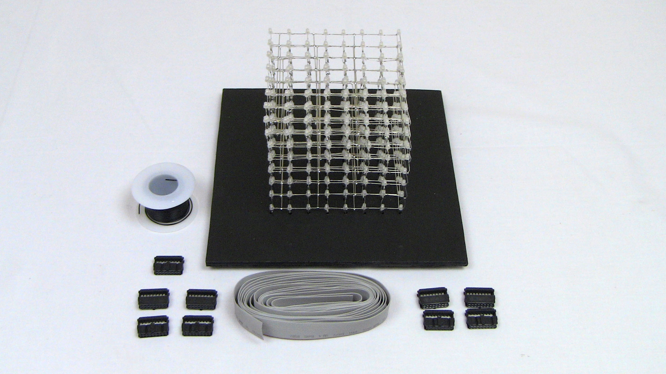
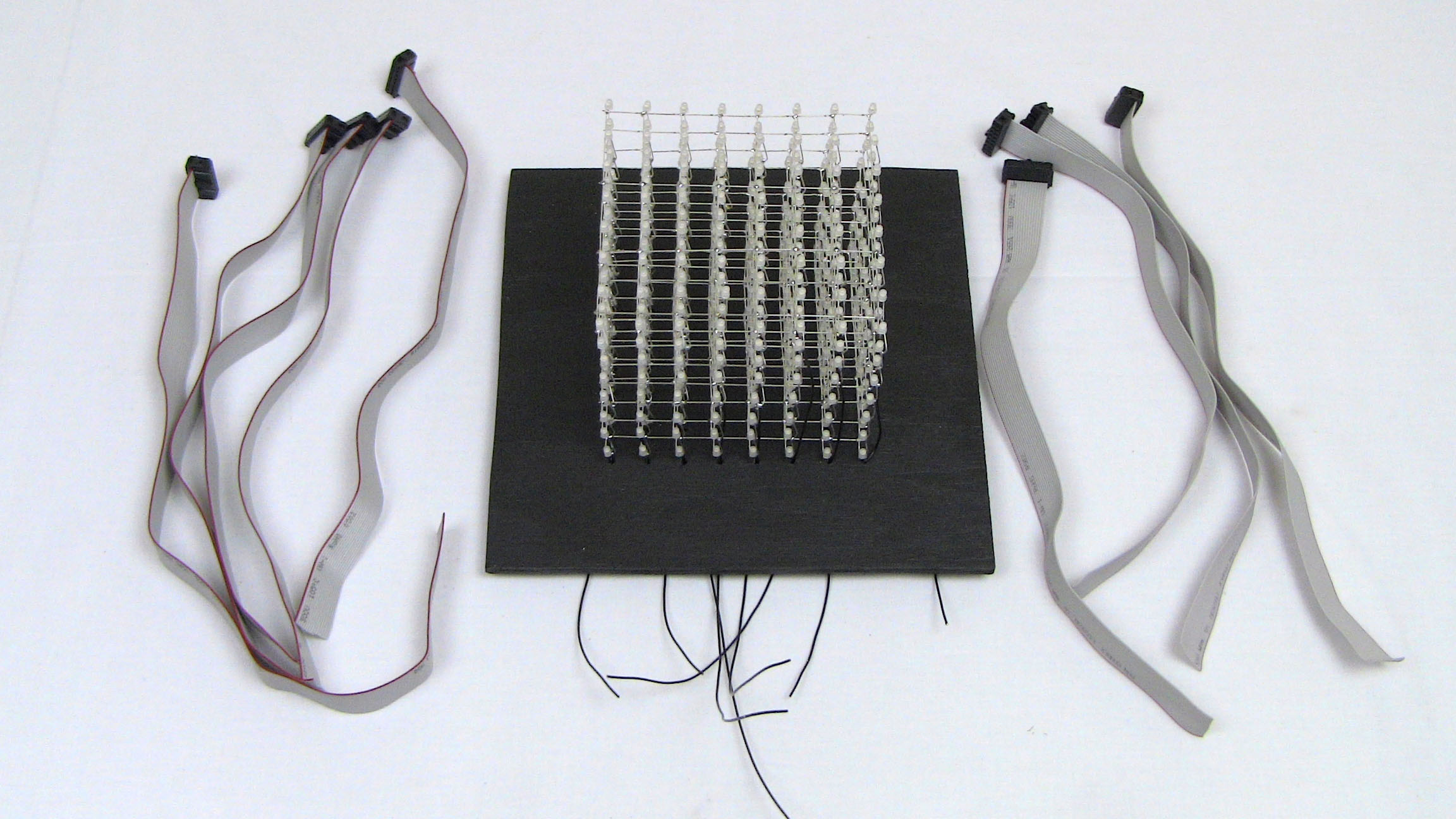
The 8x8x8 LED Cube and Some Cables
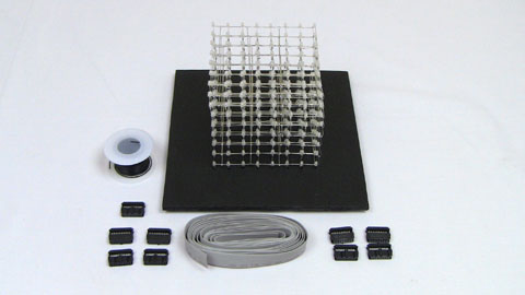
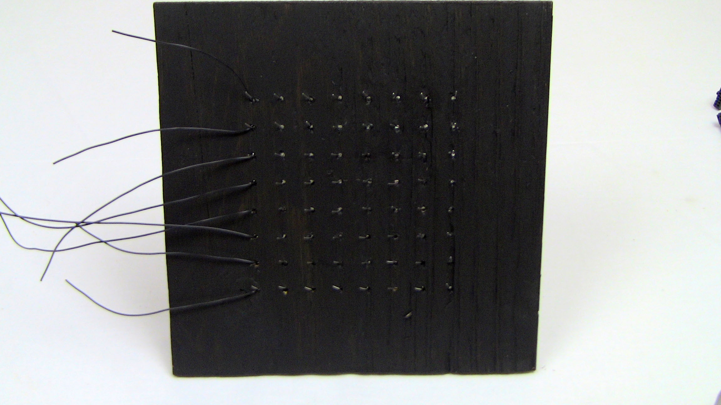
Below you can see our 8x8x8 LED Cube as we built it earlier, some 16 pin connectors, 16 wire ribbon cable, black wire and we also stained the original wooden template a dark black color, looks much nicer don't you think?
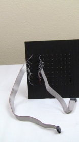
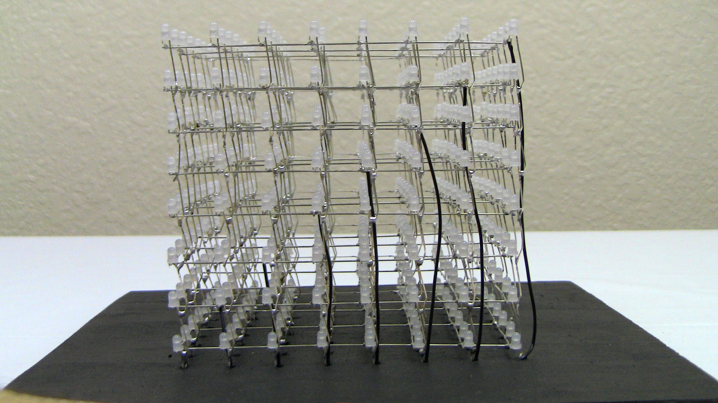
· So the first real step here is to get the LED cube into the template. Even though the holes are much bigger than the LED anode wires, it's rather challenging to get the 64 wires to work together and slide into the template.

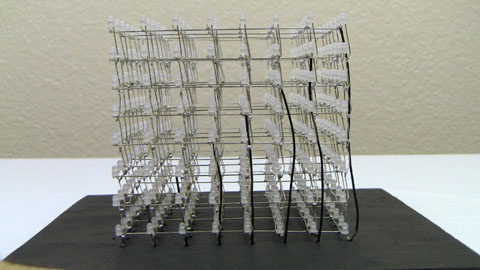
·Using the black wire, we made connections to each of the 8 horizontal layers and we routed the wire down through the holes along side the LED. These wires will be used with the cathode/layer control.
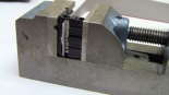
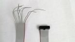
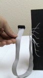
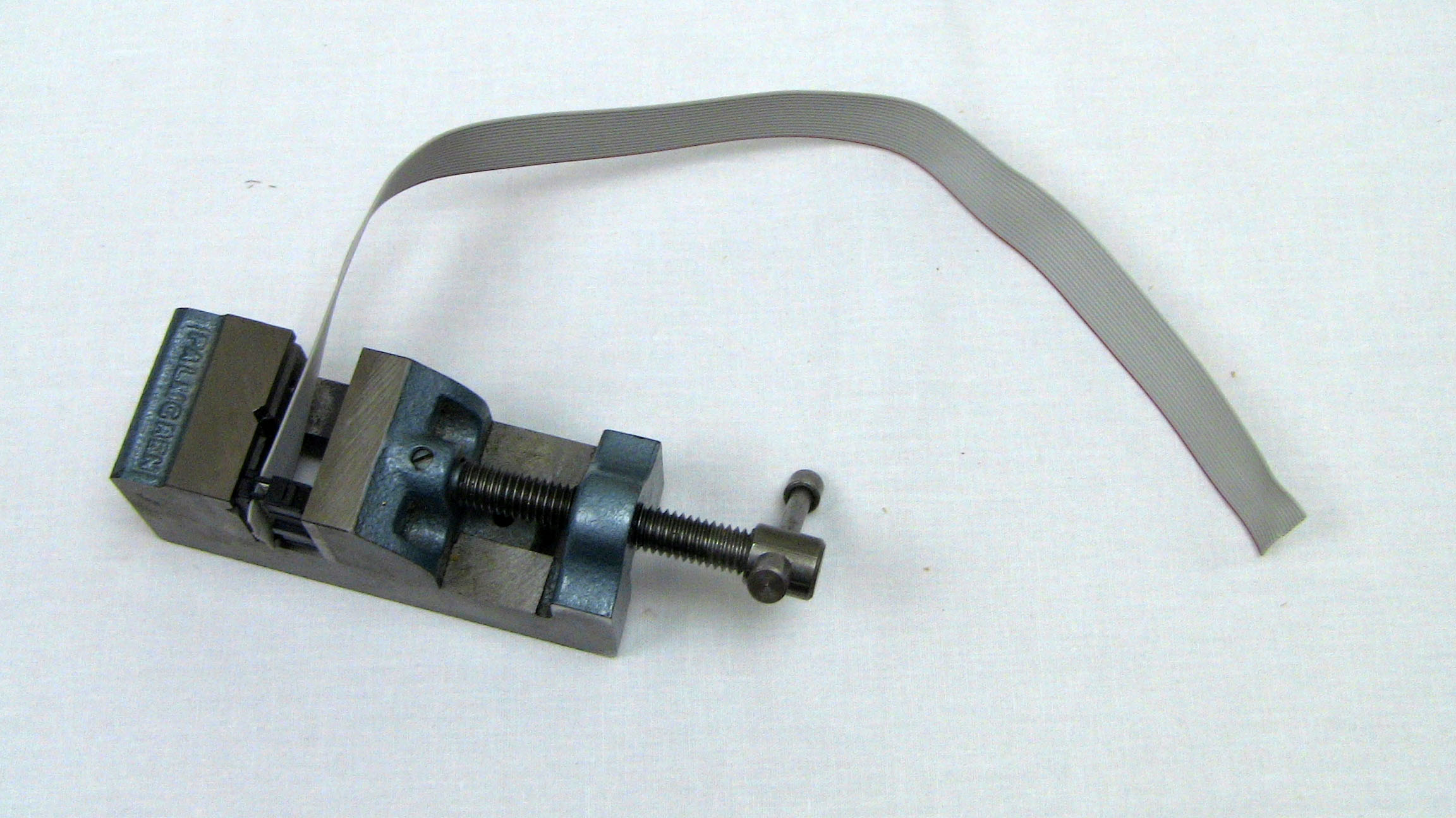
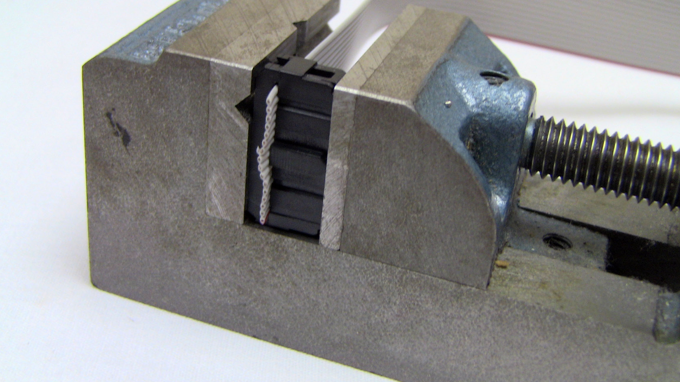
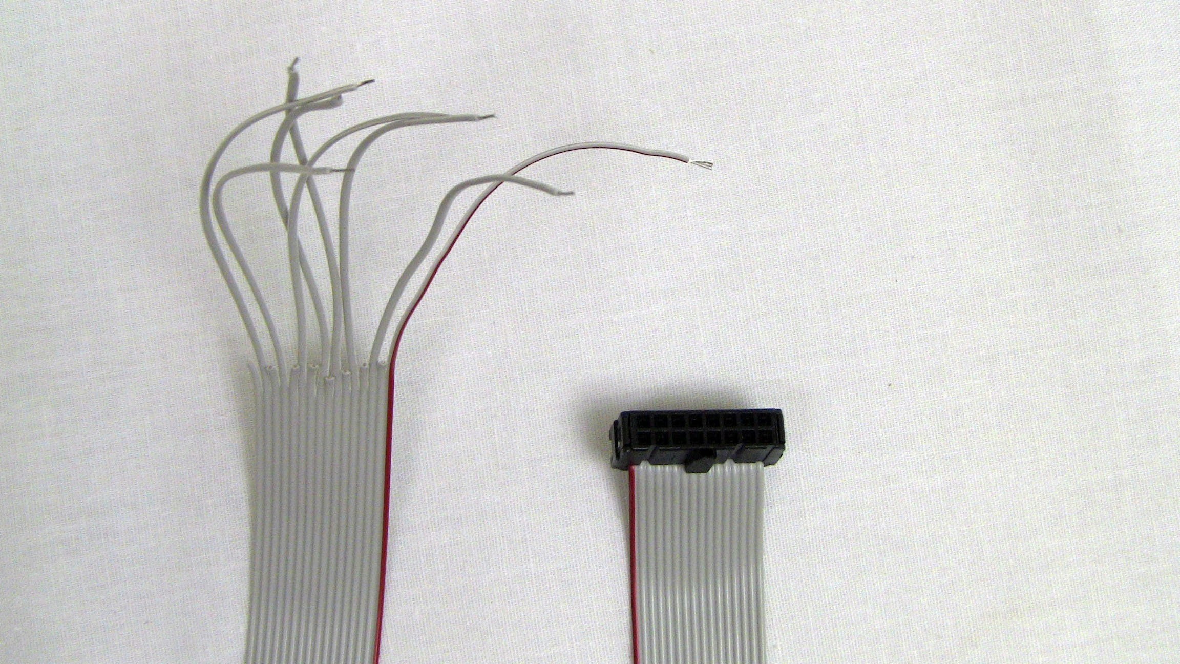
·Next, we need to make some wires. Using a vise, insert the wire to the back side of the connector and then use the vise to push the connector together. Ta-da! Now you have a cable.

·Since the 16 wire ribbon cable was 10 feet long, each strip of wire is just over 1 foot long since we needed to make 9 cables in total. Now that all the wires are made and the connections are ready, let's get soldering.
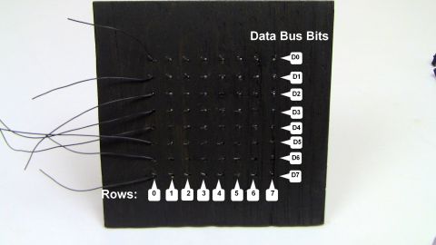
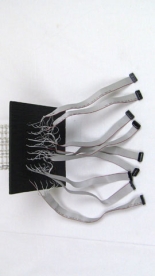
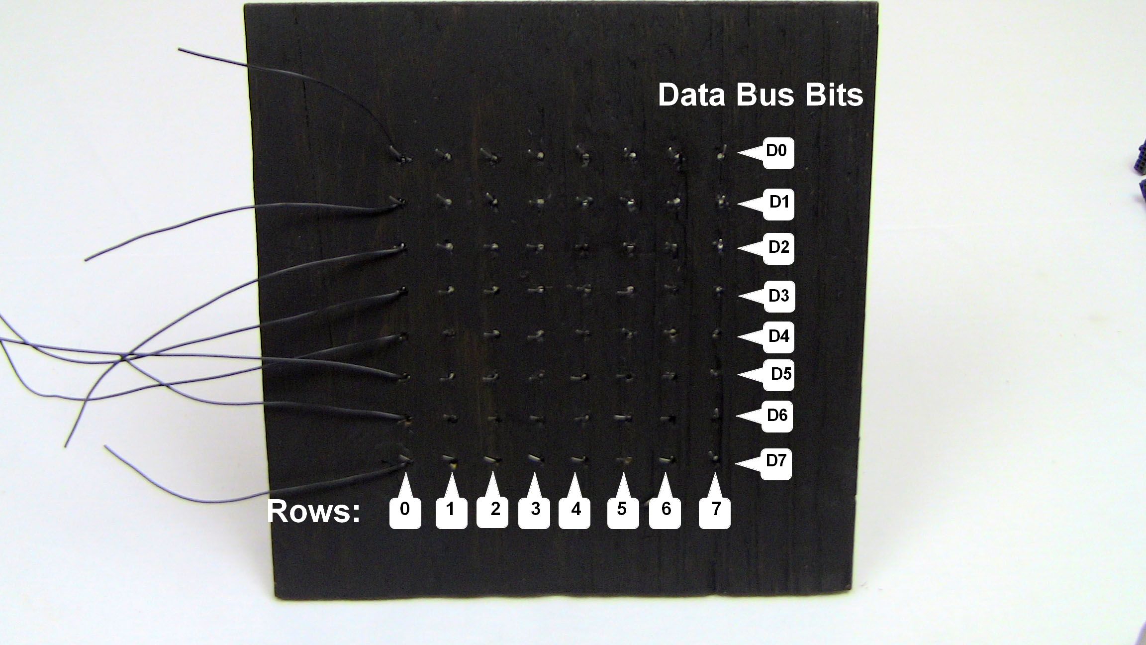
·The way to connect the bottom of the grid has a method to the madness. Each row (I was loooking at this picture side-ways when writing this) is labeled 0 to 7. This corresponds to one of each of the 74HC574 IC's. Row 0 would be the chip that the 74HC138 address decoder connects Y0 to and that follows true all the way up to Row 7 and the address decoder's Y7 pin connecting to the clock input of the 8th 74HC574. Data bus bits, connect 1 to 1. D0 connects to Q0 all the way down to D7 connecting to Q7 of the 74HC574.
Lastly, the 8 cathode control wires connect in a similarly methodical fashion. The Layer 1 wire, connects to pin 1 of the cathod control header, all the way up to pin 8 connecting to layer 8's black wire. Anyway, stay tuned through the next few pictures and you'll get the idea.
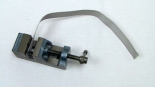
·Since we only need 8 wires, choose one side (top or bottom) of the connector that you plan to connect to the 8 pin header on the board and then cut off every other wire to make it obvious which wires at the end of the cable are the active ones.
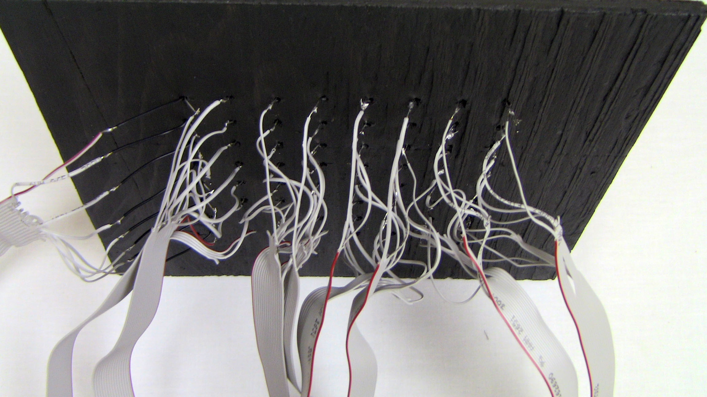
·Take your time, tin the leads of the cable wire and get some solder on the bottom of the LEDs and one-by-one connect each of the 8 rows of LEDs to a connector.
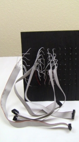
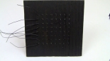
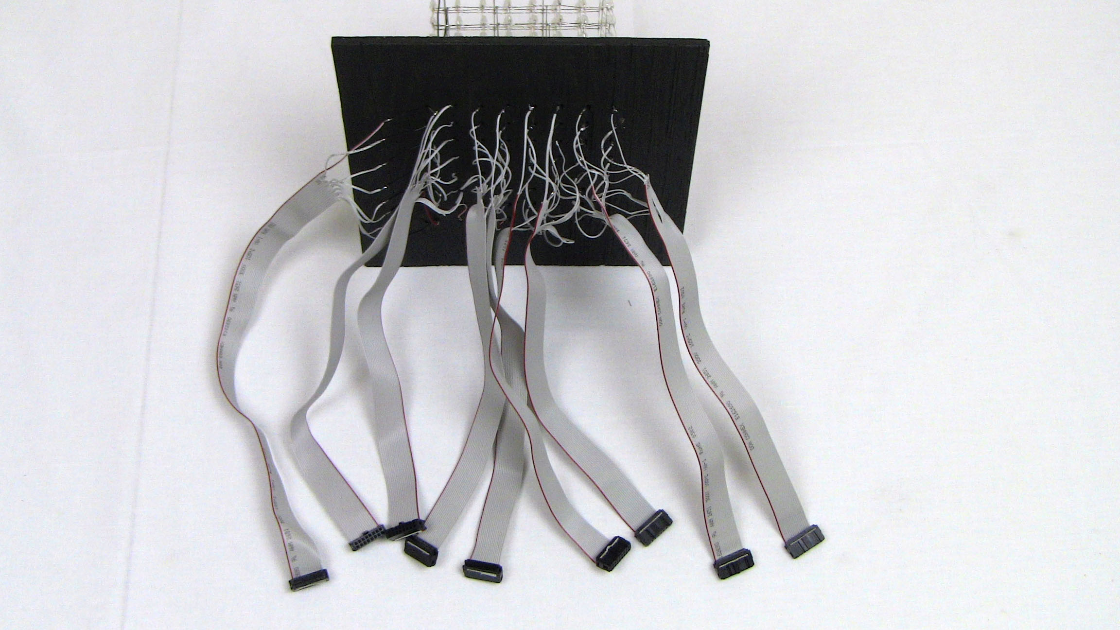
·After they're all on, it should look something like this. 9 connectors, 8 for LED anode connections and 1 for each horizontal layer's cathod of the LEDs

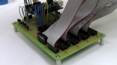
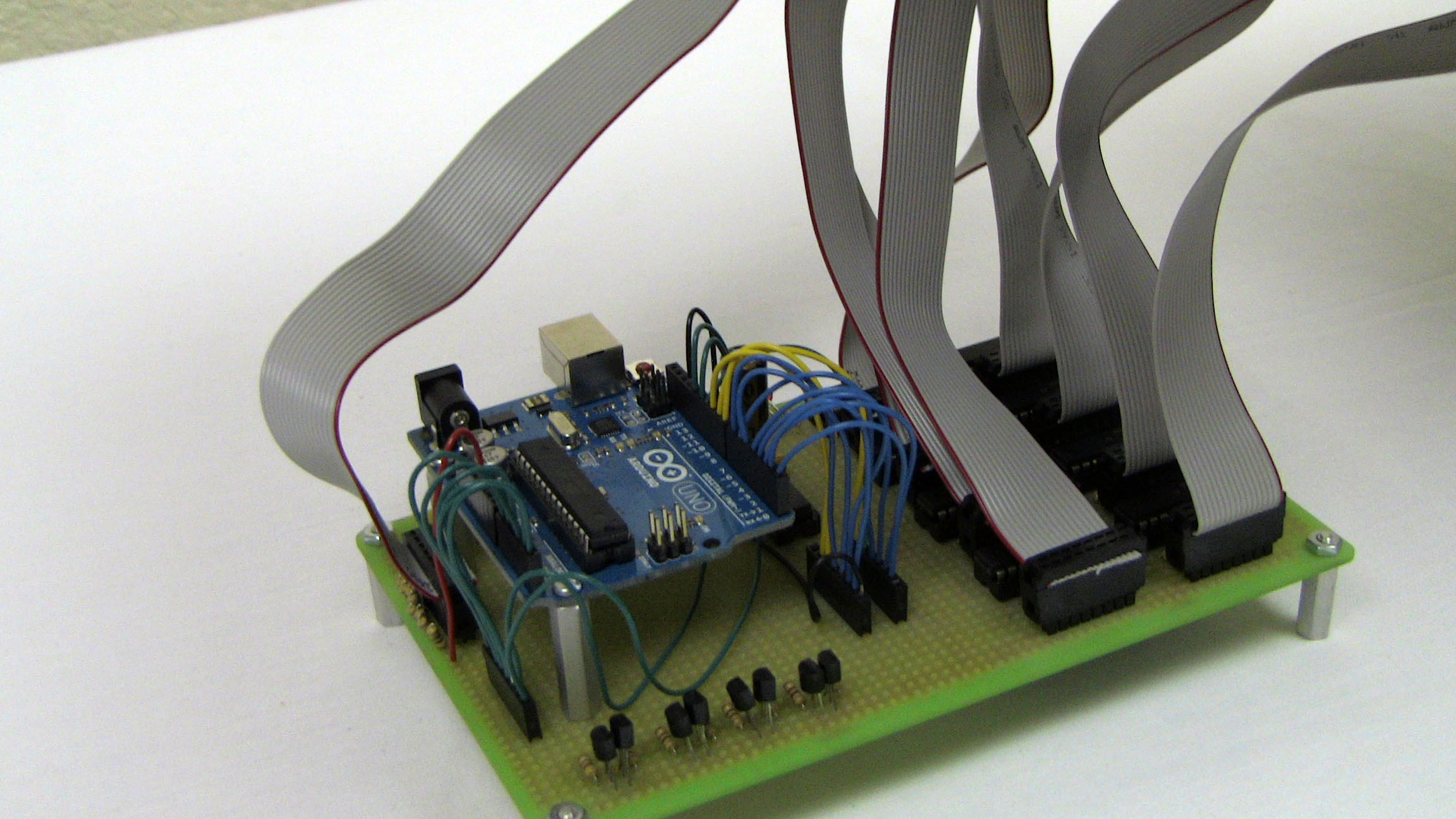
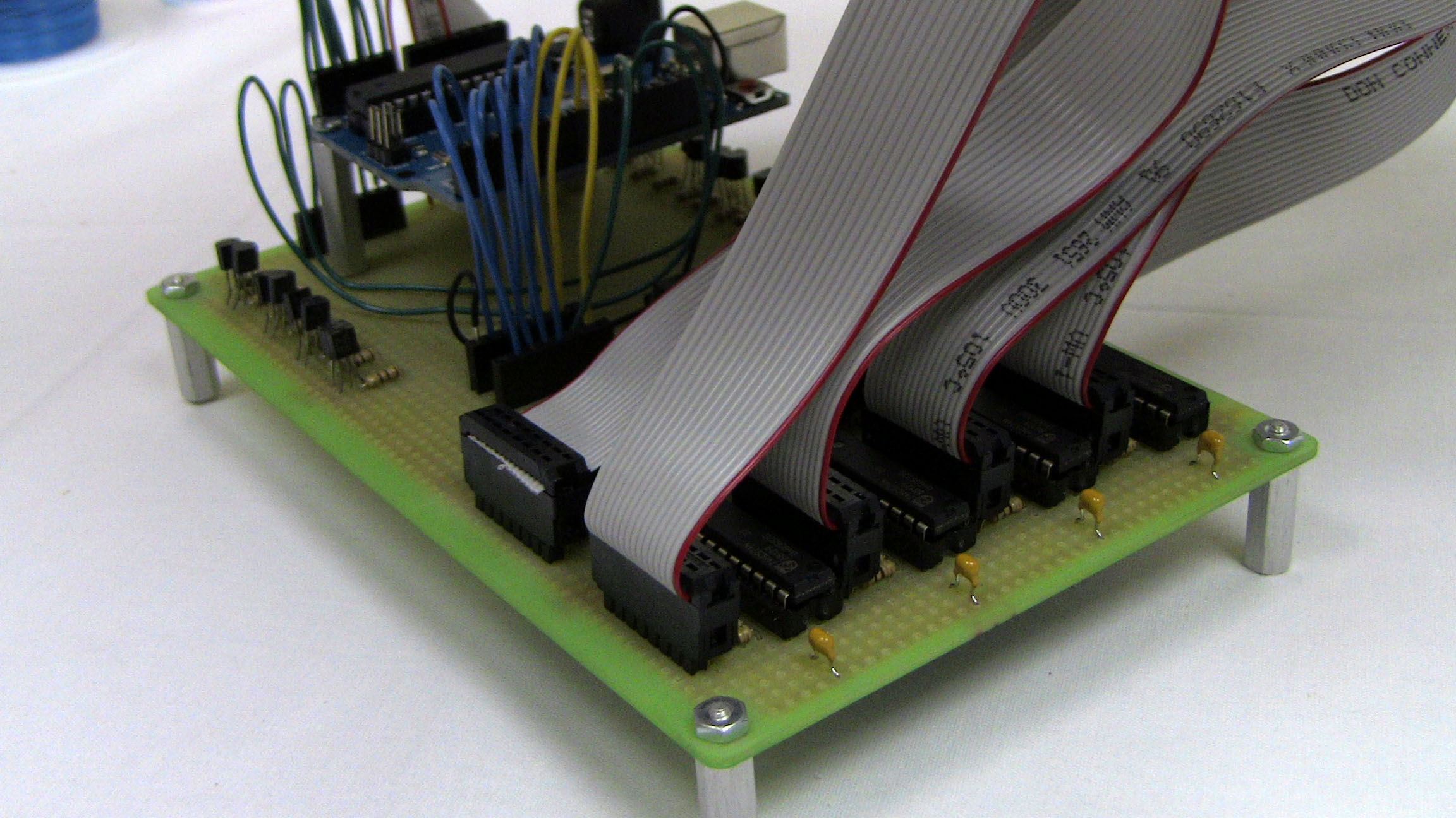
·Since we've got the cabling done you can actually connect all the cables to the drive board and give the system a test run.

·However we're not quite finished. We wanted to make a nice enclosure for the project, so let's do that real quick then call the hardware complete.
At this point we've built the complete circuit and our LED cube. Now we need to build up some cables and connect them up to the LED cube so our LED drive board can work its magic. So let's do it!
The 8x8x8 LED Cube and Some Cables
Below you can see our 8x8x8 LED Cube as we built it earlier, some 16 pin connectors, 16 wire ribbon cable, black wire and we also stained the original wooden template a dark black color, looks much nicer don't you think?
· So the first real step here is to get the LED cube into the template. Even though the holes are much bigger than the LED anode wires, it's rather challenging to get the 64 wires to work together and slide into the template.
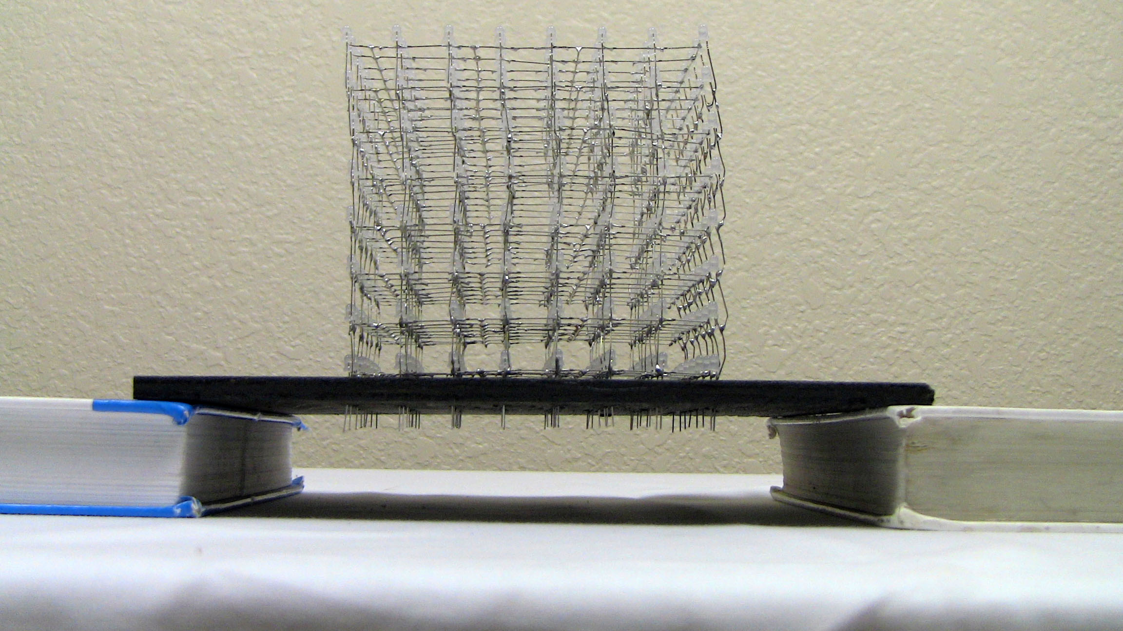
·Using the black wire, we made connections to each of the 8 horizontal layers and we routed the wire down through the holes along side the LED. These wires will be used with the cathode/layer control.
·Next, we need to make some wires. Using a vise, insert the wire to the back side of the connector and then use the vise to push the connector together. Ta-da! Now you have a cable.

·Since the 16 wire ribbon cable was 10 feet long, each strip of wire is just over 1 foot long since we needed to make 9 cables in total. Now that all the wires are made and the connections are ready, let's get soldering.
·The way to connect the bottom of the grid has a method to the madness. Each row (I was loooking at this picture side-ways when writing this) is labeled 0 to 7. This corresponds to one of each of the 74HC574 IC's. Row 0 would be the chip that the 74HC138 address decoder connects Y0 to and that follows true all the way up to Row 7 and the address decoder's Y7 pin connecting to the clock input of the 8th 74HC574. Data bus bits, connect 1 to 1. D0 connects to Q0 all the way down to D7 connecting to Q7 of the 74HC574.
Lastly, the 8 cathode control wires connect in a similarly methodical fashion. The Layer 1 wire, connects to pin 1 of the cathod control header, all the way up to pin 8 connecting to layer 8's black wire. Anyway, stay tuned through the next few pictures and you'll get the idea.
·Since we only need 8 wires, choose one side (top or bottom) of the connector that you plan to connect to the 8 pin header on the board and then cut off every other wire to make it obvious which wires at the end of the cable are the active ones.
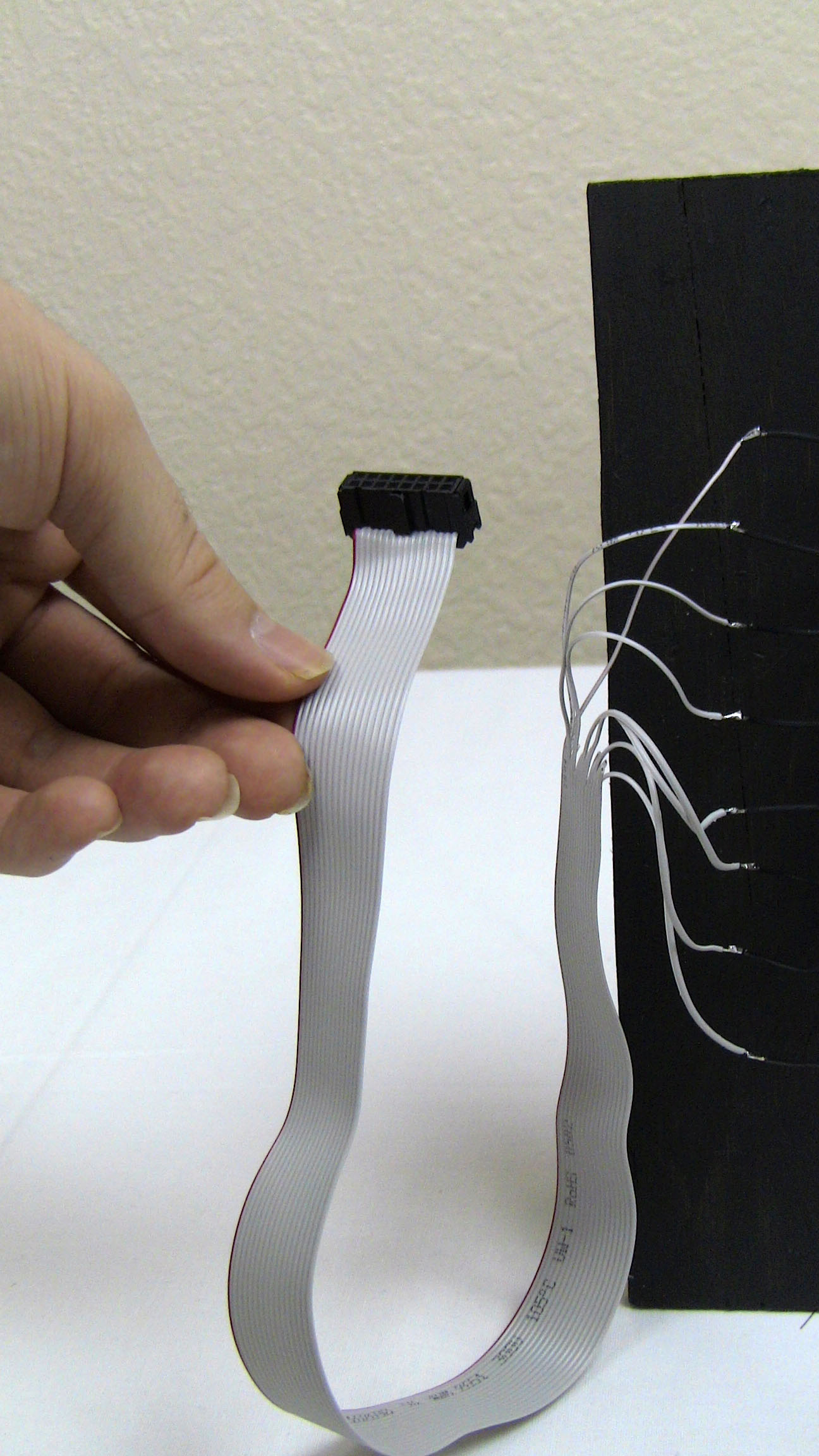
·Take your time, tin the leads of the cable wire and get some solder on the bottom of the LEDs and one-by-one connect each of the 8 rows of LEDs to a connector.


·After they're all on, it should look something like this. 9 connectors, 8 for LED anode connections and 1 for each horizontal layer's cathod of the LEDs
·Since we've got the cabling done you can actually connect all the cables to the drive board and give the system a test run.
·However we're not quite finished. We wanted to make a nice enclosure for the project, so let's do that real quick then call the hardware complete.