Kit Schematic Overview
The Club Jameco kit included a few schematics in their instructions PDF. You can see a copy of them below (hopefully they don't mind that I copied them over here):
Schematic Specifics
LED Driver Board Circuit
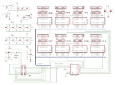
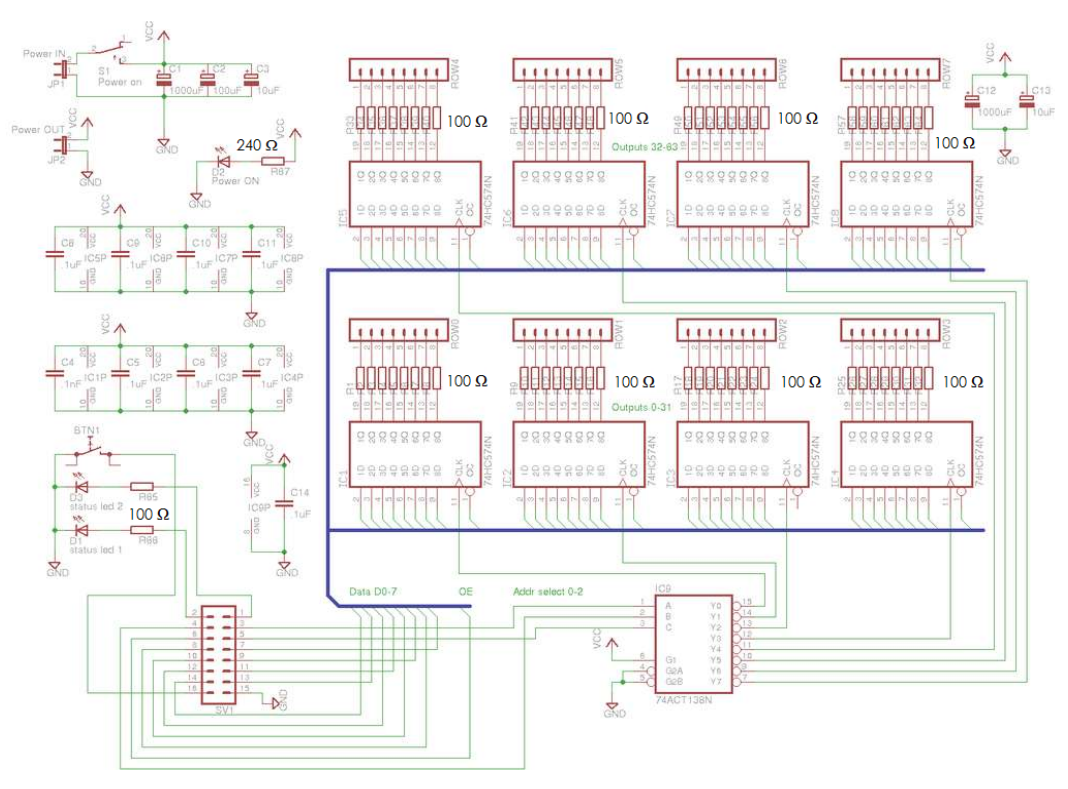
The first circuit is the schematic of the LED Driver board. This circuit consists of the address selector (74HC138), the 8 data buffers (74HC574) with a 9-bit data bus, control connector, power circuit and power LED. The schematic also has some extra power circuitry, switches and buttons that aren't included in the kit.
Cathode Control And Arduino Connections
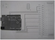
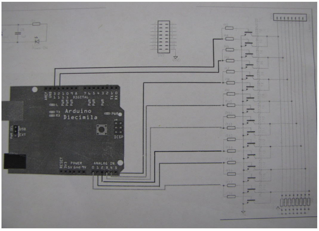
The other schematic included in the instructions is the cathode control and arduino connection circuit. It shows you how the Arduino should be connected to the LED Driver board connector, but it didn't show you how to connect the Arduino to the cathode control connector which bothered me.
Issues
The LED Driver board circuit doesn't do a great job showing you which bus lines go to which pin on the connector which can be frustrating. Similarly, the schematic is split up into two seperate documents which bugged me, perhaps I'm just picky. These and other issues led me to rebuild the schematic (on the next page) so that it is a little more clear for everyone who wants to build an 8x8x8 LED Cube controlled by an Arduino.
The Club Jameco kit included a few schematics in their instructions PDF. You can see a copy of them below (hopefully they don't mind that I copied them over here):
Schematic Specifics
LED Driver Board Circuit
The first circuit is the schematic of the LED Driver board. This circuit consists of the address selector (74HC138), the 8 data buffers (74HC574) with a 9-bit data bus, control connector, power circuit and power LED. The schematic also has some extra power circuitry, switches and buttons that aren't included in the kit.
Cathode Control And Arduino Connections
The other schematic included in the instructions is the cathode control and arduino connection circuit. It shows you how the Arduino should be connected to the LED Driver board connector, but it didn't show you how to connect the Arduino to the cathode control connector which bothered me.
Issues
The LED Driver board circuit doesn't do a great job showing you which bus lines go to which pin on the connector which can be frustrating. Similarly, the schematic is split up into two seperate documents which bugged me, perhaps I'm just picky. These and other issues led me to rebuild the schematic (on the next page) so that it is a little more clear for everyone who wants to build an 8x8x8 LED Cube controlled by an Arduino.