Project Info
Author: Chris
Difficulty: Medium
Time Invested: 6 Hours
Prerequisites:
Take a look at the above
articles before continuing
to read this article.
Author: Chris
Difficulty: Medium
Time Invested: 6 Hours
Prerequisites:
Take a look at the above
articles before continuing
to read this article.
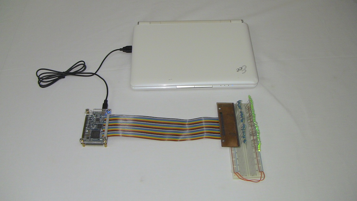
This article will go step-by-step through the process of designing a PCB that breaksout the 40 pin expansion header on the DE0-Nano demo board. The PCB will easily connect to a breadboard where you have access to each individual I/O pin.
Purpose & Overview of this project
Since I've used the DE0-Nano demo board for many things already, I was frustred that I could never use the expansion ports for prototyping, so the idea to build an expansion breakout board came to life. The goal here is to have accces to each of the 40 pins on a breadboard so that we can use them for prototyping. Alternatively, once we have the breakout board designed it will serve as a blue-print for future boards that connect to the DE0-Nano expansion port.
To create this PCB we will use the eagle schematic and layout tool using as few parts on the board as possible. That way we can get it working faster. To test that the expansion port works we'll put some LED fading code from a previous pyro article and connect each individual I/O pin with an LED.