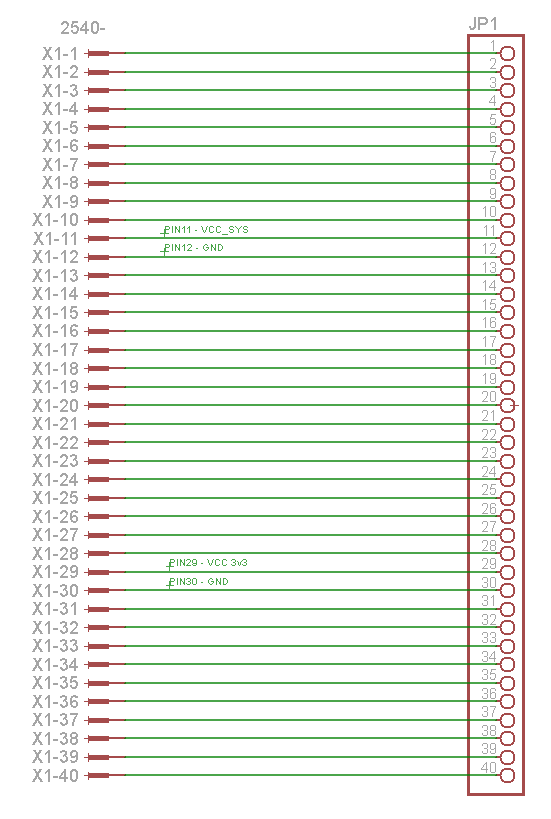
Schematic Overview
The schematic for breakout boards is thankfully simple. It's usually connector to connector which is two circuit symbols and a bunch of wires. It's important to note that 4 lines are actually very special. There are two power connections and two ground connections. You don't want to short these together, so I marked them on the schematic.
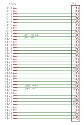
View Full Schematic
Schematic Specifics
Single Row 40 Pin Header
The left hand side of the schematic represents the single row header connector that will connect to the breadboard.
Dual Row 40 Pin Header
The right hand side of the schematic shows the connector that is a dual row header that will connect to the DE0-Nano expansion port.
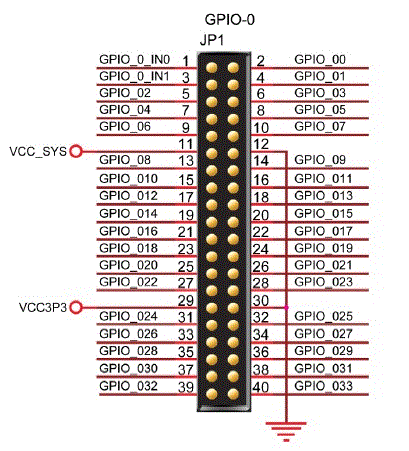
DE0 Nano Expansion Port
The DE0 Nano's expansion port has 40 pins. 34 pins are outputs, 4 pins are input, 2 ground connections, 1 System VCC and 1 3.3V VCC. The picture below shows you what pin has what functionality so that when we connect the expansion port to a breadboard, we can properly map pin-to-pin.
The schematic for breakout boards is thankfully simple. It's usually connector to connector which is two circuit symbols and a bunch of wires. It's important to note that 4 lines are actually very special. There are two power connections and two ground connections. You don't want to short these together, so I marked them on the schematic.
View Full Schematic
Schematic Specifics
Single Row 40 Pin Header
The left hand side of the schematic represents the single row header connector that will connect to the breadboard.
Dual Row 40 Pin Header
The right hand side of the schematic shows the connector that is a dual row header that will connect to the DE0-Nano expansion port.
DE0 Nano Expansion Port
The DE0 Nano's expansion port has 40 pins. 34 pins are outputs, 4 pins are input, 2 ground connections, 1 System VCC and 1 3.3V VCC. The picture below shows you what pin has what functionality so that when we connect the expansion port to a breadboard, we can properly map pin-to-pin.