Project Info
Author: Chris
Difficulty: Easy
Time Invested: 4 Hours
Prerequisites:
Take a look at the above
tutorials before continuing
to read this tutorial.
Author: Chris
Difficulty: Easy
Time Invested: 4 Hours
Prerequisites:
Take a look at the above
tutorials before continuing
to read this tutorial.
Breakout boards usually only have 1 part on them surrounded by breadboard friendly SIP holes to which you can easily solder a connector or wires. The whole point of this board is to give designers or debuggers easy access to each individual pin on the part. For this tutorial I'm going to make a breakout board for an 802.3 ethernet port.
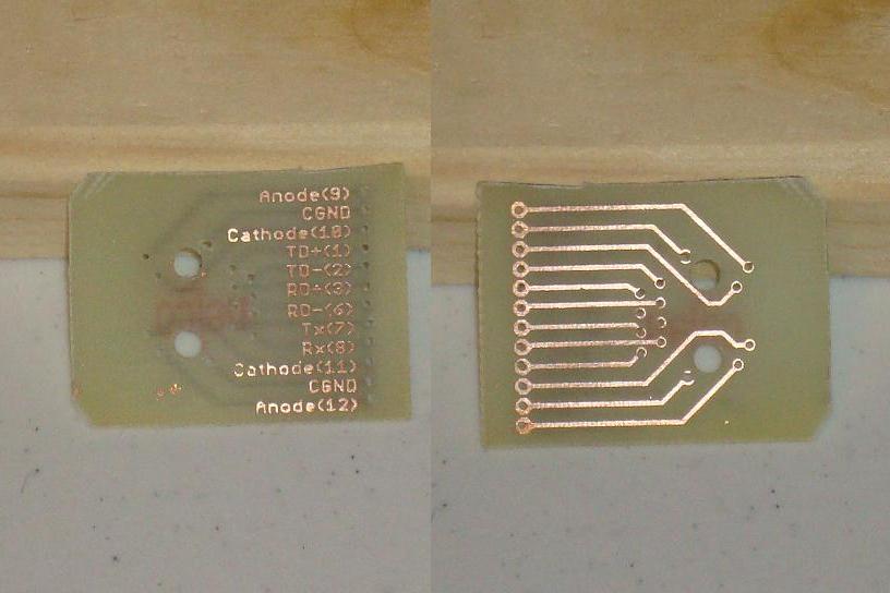

Purpose & Overview of this project
The purpose of this project is to design a breakout board for an ethernet connector I have. The part doesn't exist in my schematic/layout tool so I'll have to create my own footprint. The final result should be able to fit easily into a breadboard because that's what I'm using to prototype some ethernet work.
While the part I'm making a breakout board for isn't exactly small, breakout boards are more commonly seen with small packaged parts because their I/O pins are too small or too inconvienient to probe by hand, so you need to connect larger wires to it, thus we have the solution: the breakout board.