Project Info
Author: Chris
Difficulty: Easy
Time Invested: 2 Hours
Prerequisites:
Take a look at the above
articles before continuing
to read this article.
Author: Chris
Difficulty: Easy
Time Invested: 2 Hours
Prerequisites:
Take a look at the above
articles before continuing
to read this article.
This article will use the same theory from the microcontroller version of fading LEDs but we'll use the CPLD Dev Board seen last in the connecting ADCs to FPGAs article. There we connected up a 10 LED Bar which we will use in this article to show how to create that fading-in and fading-out effect via PWM.
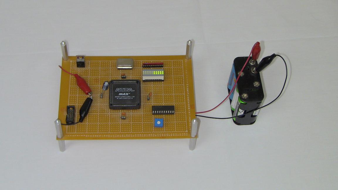
Purpose & Overview Of This Project
The goal of this project is to create a stand-alone output system that fades LEDs in and out. A CPLD hardware module will need to be created that can use a standard period cycle and vary the PWM output so that an LED's brightness varies in a linear fashion.
To reach this goal, we will use the CPLD Dev Board that has an EPM7128 CPLD on it but any FPGA or CPLD can be substituted. On the 10 LED bar, the LEDs should fade in and out in a specific pattern. While the first 5 LEDs on the bar fade-in, the last 5 LEDs on the bar should be fading out. This way the two sides of the LED bar will fade opposite each other, creating a Yin-Yang effect of opposites.