Build The Schematic
If you've ever seen a schematic of an IC what we're about to build will be familiar. Using basic logic gates we'll build a program to switch some LEDs off and on using switches on the DE2 board.
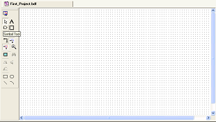
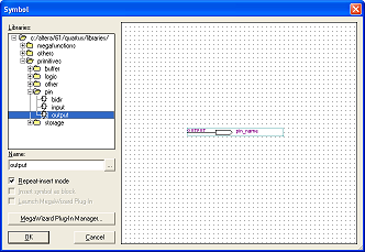
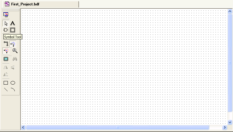
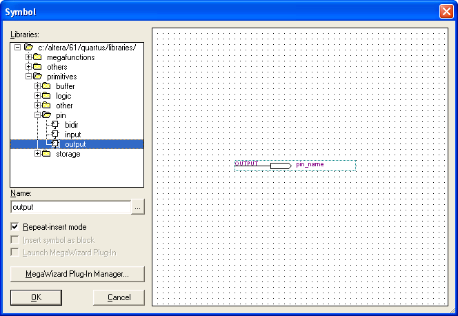
Focusing on the schematic, first click the Symbol Tool. »
These are the five digital items we'll be using:
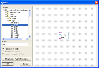
This is the 'AND Gate' and will be used in our design »
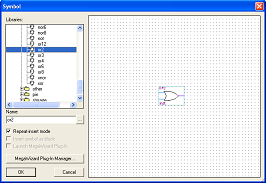
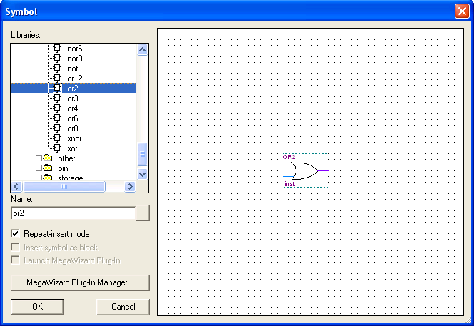
Next is the 'OR Gate' »
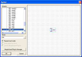
This is a 'NOT Gate' »
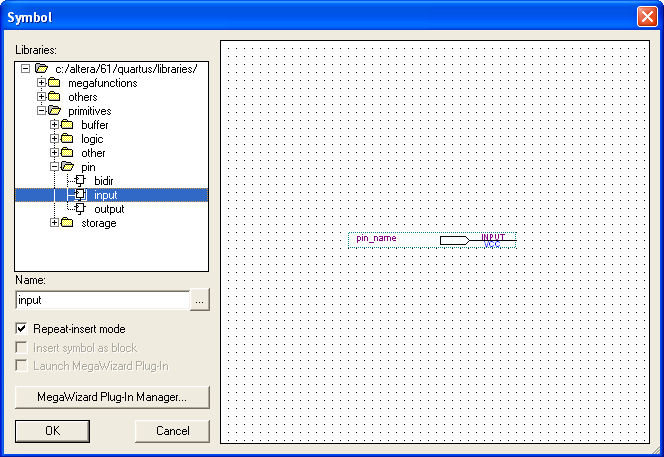
This is an input pin that we'll specify later on »

This is an output pin that we'll specify later on »
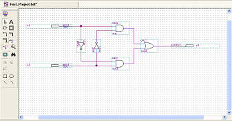
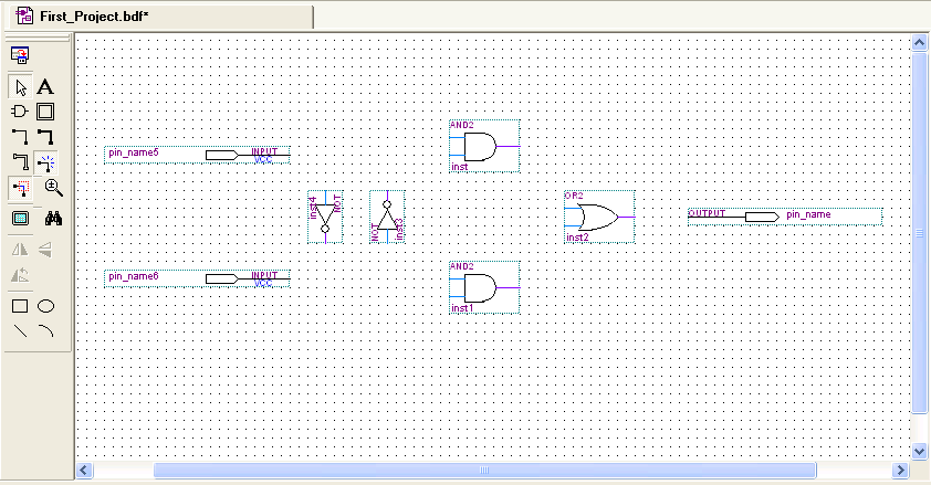
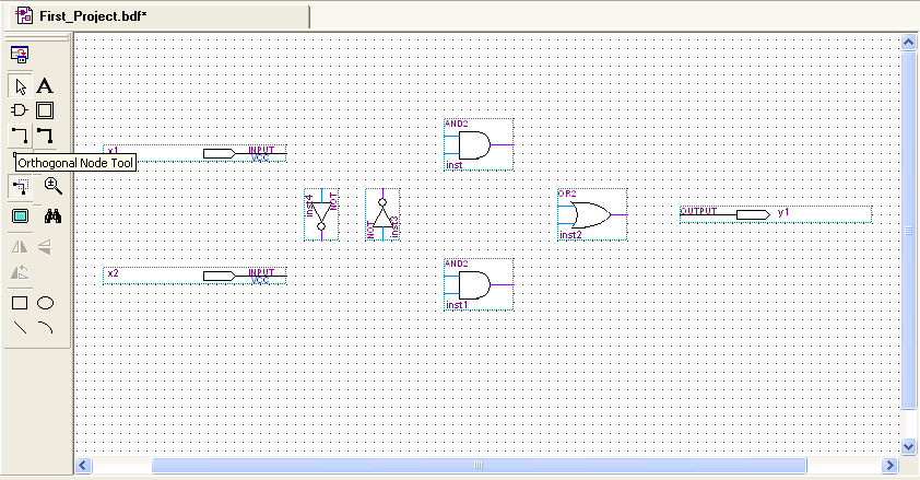
Using these 5 items, click & drag to create a schematic that looks like this »

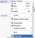
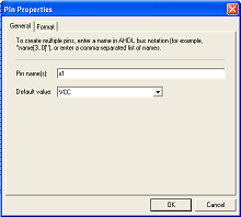
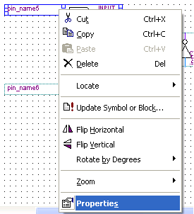
Name the input & output pins by right clicking & going to properties »
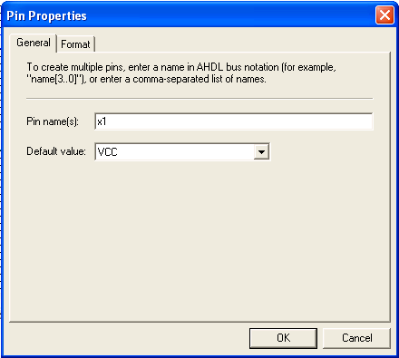
We'll call the inputs x1 & x2 and the output y1 »
Now use the 'Orthogonal Node Tool' to wire the gates together »
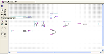
This is how it should be wired up »
The programming is done! The schematic method of programming is quite painless. Now let's move on and compile this!
If you've ever seen a schematic of an IC what we're about to build will be familiar. Using basic logic gates we'll build a program to switch some LEDs off and on using switches on the DE2 board.
Focusing on the schematic, first click the Symbol Tool. »
These are the five digital items we'll be using:
This is the 'AND Gate' and will be used in our design »

Next is the 'OR Gate' »
This is a 'NOT Gate' »

This is an input pin that we'll specify later on »
This is an output pin that we'll specify later on »
Using these 5 items, click & drag to create a schematic that looks like this »
Name the input & output pins by right clicking & going to properties »
We'll call the inputs x1 & x2 and the output y1 »
Now use the 'Orthogonal Node Tool' to wire the gates together »
This is how it should be wired up »
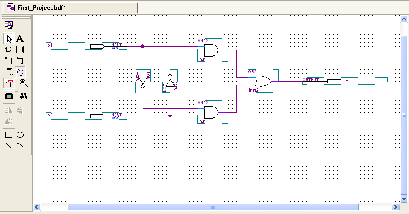
The programming is done! The schematic method of programming is quite painless. Now let's move on and compile this!