FPGA/CPLD ADC Interface Overview
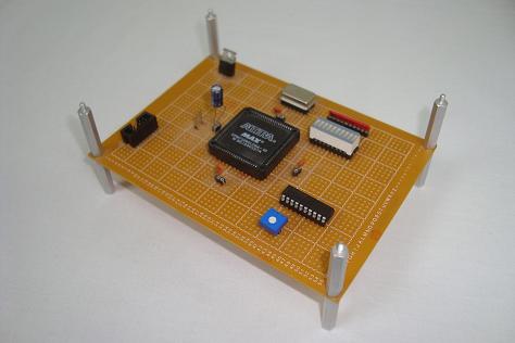
We set out in this article to build a simple system that can interface with an analog to digital converter, and then to display that digital value on a set of LEDs. A MAX150 was used with an LED bar, a CPLD with some custom VHDL created the interface between all of these components and the system worked as expected. Sure, we only used a trimpot for analog voltages input to the ADC, but we have to start with boring stuff before we can get to fancy sensors!
What To Do Now
Now that you have a system that can understand analog voltages, many new doors have opened to you. Perhaps the best next step is to find some sensor that outputs an analog voltage, like a temperature sensor, proximity sensor or accelerometer and to translate its analog output into something we can all understand. Alternatively you can move beyond the MAX150 to more complicated A/D converters that allow for multiple analog inputs.
Conclusion
The primary goals set out in the purpose were all achieved in this article. The video proved that the system worked, and all of the design resources are available in this article for the world to see. I hope you have learned how building a simple A/D interface like this one can lead you to bigger and brighter things!
If you have any further questions, I implore you...don't be shy, take a look at the forums or ask a question there. I check them out regularly and love getting comments & questions.
We set out in this article to build a simple system that can interface with an analog to digital converter, and then to display that digital value on a set of LEDs. A MAX150 was used with an LED bar, a CPLD with some custom VHDL created the interface between all of these components and the system worked as expected. Sure, we only used a trimpot for analog voltages input to the ADC, but we have to start with boring stuff before we can get to fancy sensors!

What To Do Now
Now that you have a system that can understand analog voltages, many new doors have opened to you. Perhaps the best next step is to find some sensor that outputs an analog voltage, like a temperature sensor, proximity sensor or accelerometer and to translate its analog output into something we can all understand. Alternatively you can move beyond the MAX150 to more complicated A/D converters that allow for multiple analog inputs.
Conclusion
The primary goals set out in the purpose were all achieved in this article. The video proved that the system worked, and all of the design resources are available in this article for the world to see. I hope you have learned how building a simple A/D interface like this one can lead you to bigger and brighter things!
If you have any further questions, I implore you...don't be shy, take a look at the forums or ask a question there. I check them out regularly and love getting comments & questions.