Project Info
Author: Chris
Difficulty: Medium
Time Invested: 3 Hours
Prerequisites:
Take a look at the above
articles before continuing
to read this article.
Author: Chris
Difficulty: Medium
Time Invested: 3 Hours
Prerequisites:
Take a look at the above
articles before continuing
to read this article.
In this article, we'll use the CPLD Dev Board that I assembled together years ago and add an analog to digital converter IC, along with an LED bar and some current limiting resistors for output to verify the A/D converter is working. VHDL is listed as a pre-req as we'll be using it to design our custom A/D interface.
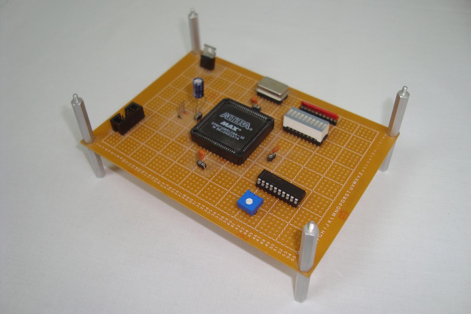
Purpose & Overview of this project
The purpose of this project is to build a system that can use a generic analog to digital converter IC to convert an analog voltage value to a digital value and then display that digital value on an LED bar. This will require a custom interface to the A/D converter IC and to the LED bar.
An Altera EPM7128 CPLD will be used and since it's already on the CPLD Dev Board it's ready to go, a MAX150 8-bit analog to digital converter IC will be used for converting analog voltages to digital values and a standard 10 green LED bar will be used with some current limiting resistors to display the converted A/D value in both a binary and straight magnitudal way.