Schematic Overview
The schematic for this tutorial was kept as simple as possible so that the focus could remain on how the touch screen works and how we interface to it. You can see the completed schematic for this project below. The main parts in the schematic are the XBee Module, MAX233a, LM7805 and LM317.
XBee Transmitter + MAX233A Interface
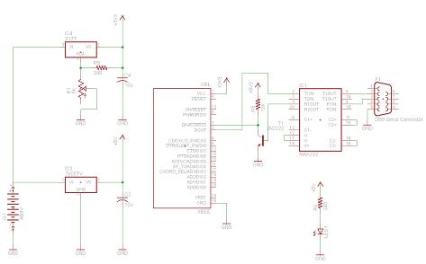
View Full Schematic
Schematic Specifics
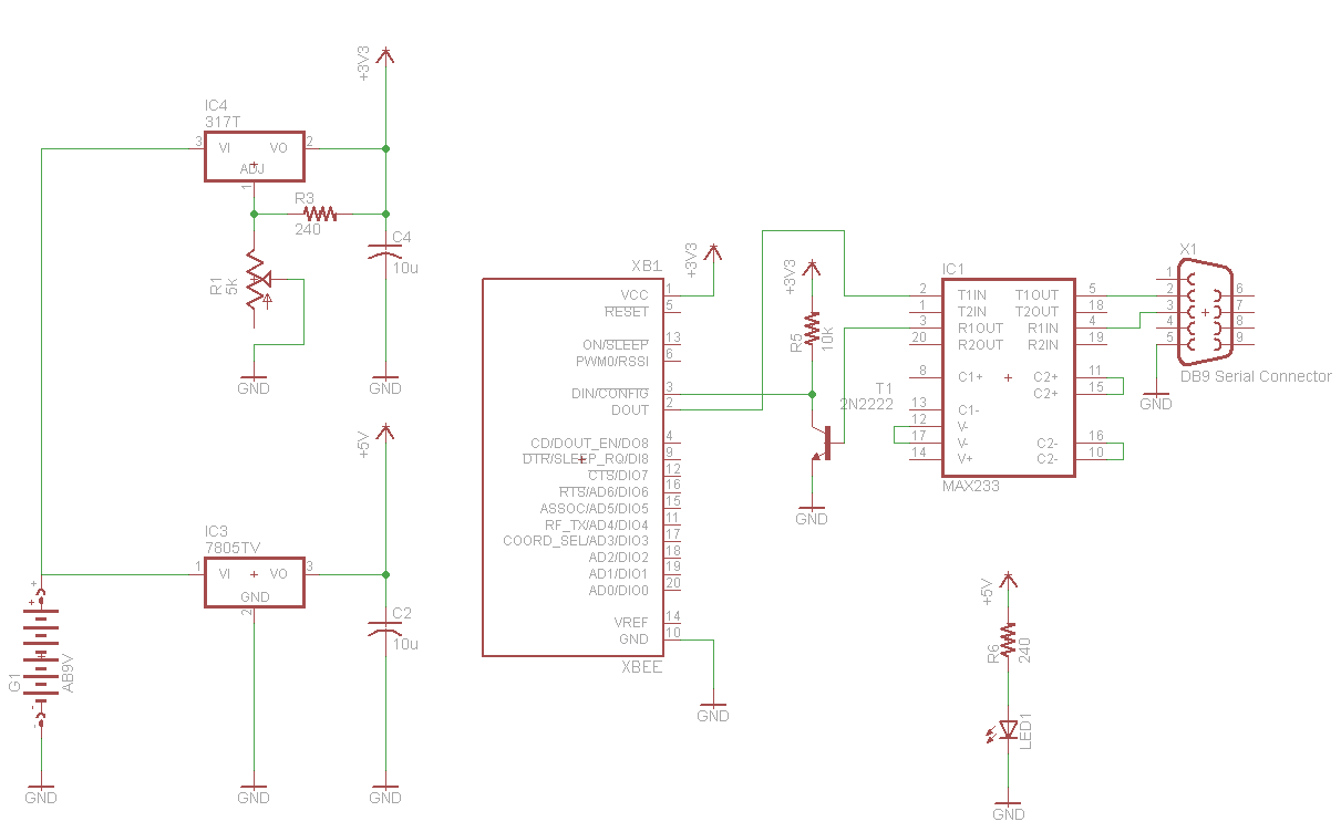
Power Regulator
The power regulation circuit is a LM7805 +5v regulator that will convert the +9v from the battery to a steady +5v output to the MAX233a. A LM317 variable regulator is also used to regulate down to +3.3v for the level shifter and to power the XBee module.
MAX233A Circuit
The microcontroller circuit consists of the PIC 18F452, it's 40 MHz crystal clock and the 10k resistor connected to pin 1, MCLR. Along with power and ground connections, these are the basic connections necessary to run the program loaded on the PIC.
2N2222 Level Shifter
Three general purpose 2n2222 transistors are used to drive each color of the Red/Green/Blue LED. This method ensures that the LED shines as bright as it should be since it's power is coming directly from the regulated voltage.
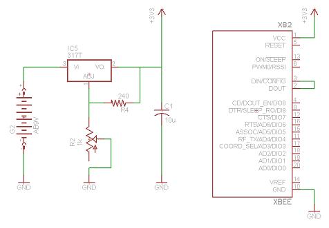
XBee Receiver
View Full Schematic
Schematic Specifics
Power Regulator
The power regulation circuit is a LM317 variable regulator that will convert the +9v from the battery to a steady +3.3v output to the XBee. A variable resistor is used to set the exact voltage output to the +3.3v we want.
XBee LoopBack Circuit
The XBee module in this circuit should have PIN 2 and PIN 3 connected together so that it can be used for the range test. Connecting the serial Din and Dout pins together means whatever data that is received, is also transmitted back, hence a loopback.
The schematic for this tutorial was kept as simple as possible so that the focus could remain on how the touch screen works and how we interface to it. You can see the completed schematic for this project below. The main parts in the schematic are the XBee Module, MAX233a, LM7805 and LM317.
XBee Transmitter + MAX233A Interface
View Full Schematic
Schematic Specifics
Power Regulator
The power regulation circuit is a LM7805 +5v regulator that will convert the +9v from the battery to a steady +5v output to the MAX233a. A LM317 variable regulator is also used to regulate down to +3.3v for the level shifter and to power the XBee module.
MAX233A Circuit
The microcontroller circuit consists of the PIC 18F452, it's 40 MHz crystal clock and the 10k resistor connected to pin 1, MCLR. Along with power and ground connections, these are the basic connections necessary to run the program loaded on the PIC.
2N2222 Level Shifter
Three general purpose 2n2222 transistors are used to drive each color of the Red/Green/Blue LED. This method ensures that the LED shines as bright as it should be since it's power is coming directly from the regulated voltage.
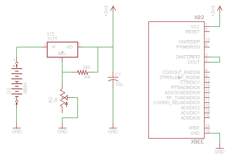
XBee Receiver
View Full Schematic
Schematic Specifics
Power Regulator
The power regulation circuit is a LM317 variable regulator that will convert the +9v from the battery to a steady +3.3v output to the XBee. A variable resistor is used to set the exact voltage output to the +3.3v we want.
XBee LoopBack Circuit
The XBee module in this circuit should have PIN 2 and PIN 3 connected together so that it can be used for the range test. Connecting the serial Din and Dout pins together means whatever data that is received, is also transmitted back, hence a loopback.