Hardware Design
This hardware section will show you how I built both circuits. First the main circuit that we will connect to a PC and then the super simple circuit that we'll use for the dual XBee range test..
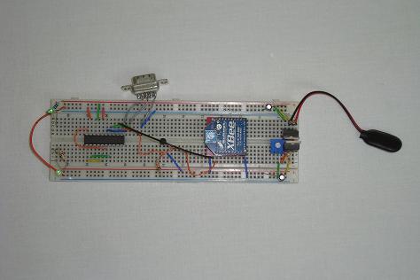
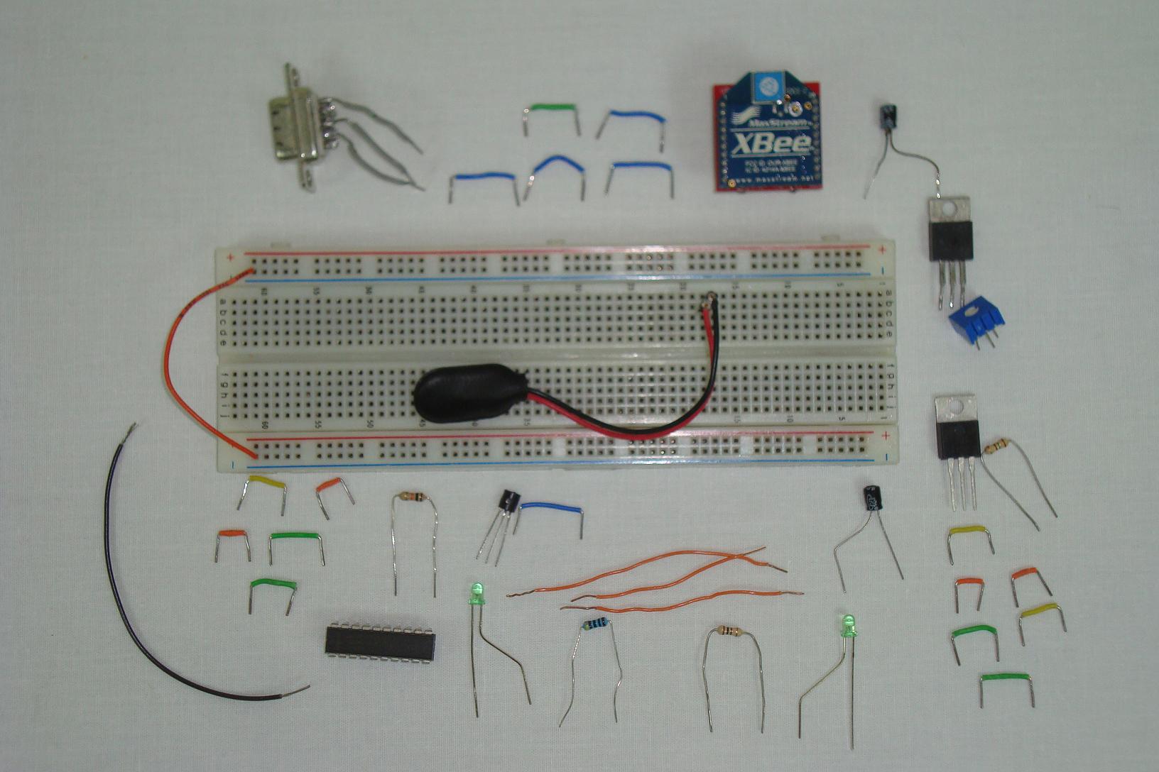
Building The Complex Circuit
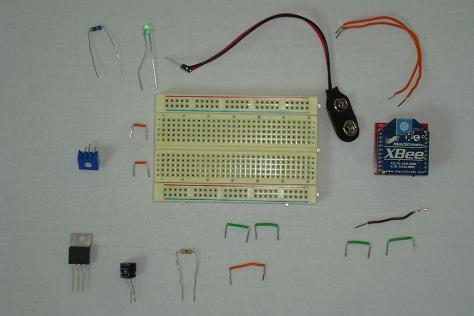
Get your parts together and follow the schematic. Each picture below will show how I connected the circuit together, in sections.
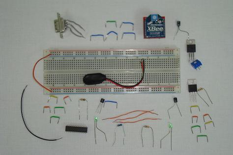
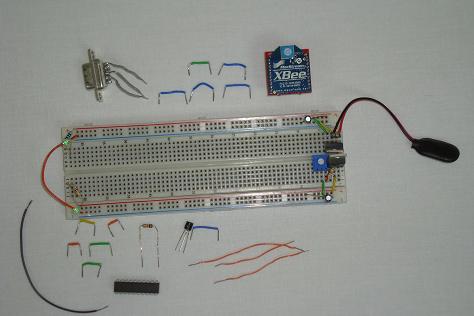
·First the +5v//+3.3v power regulator and power LEDs are added.
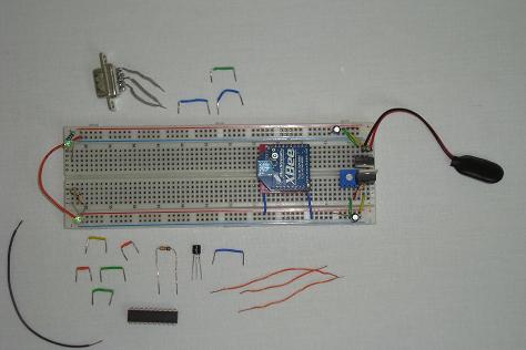
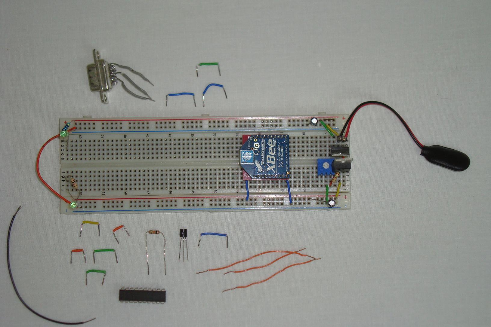
·Next, the XBee is added and connected to +3.3v power and ground.
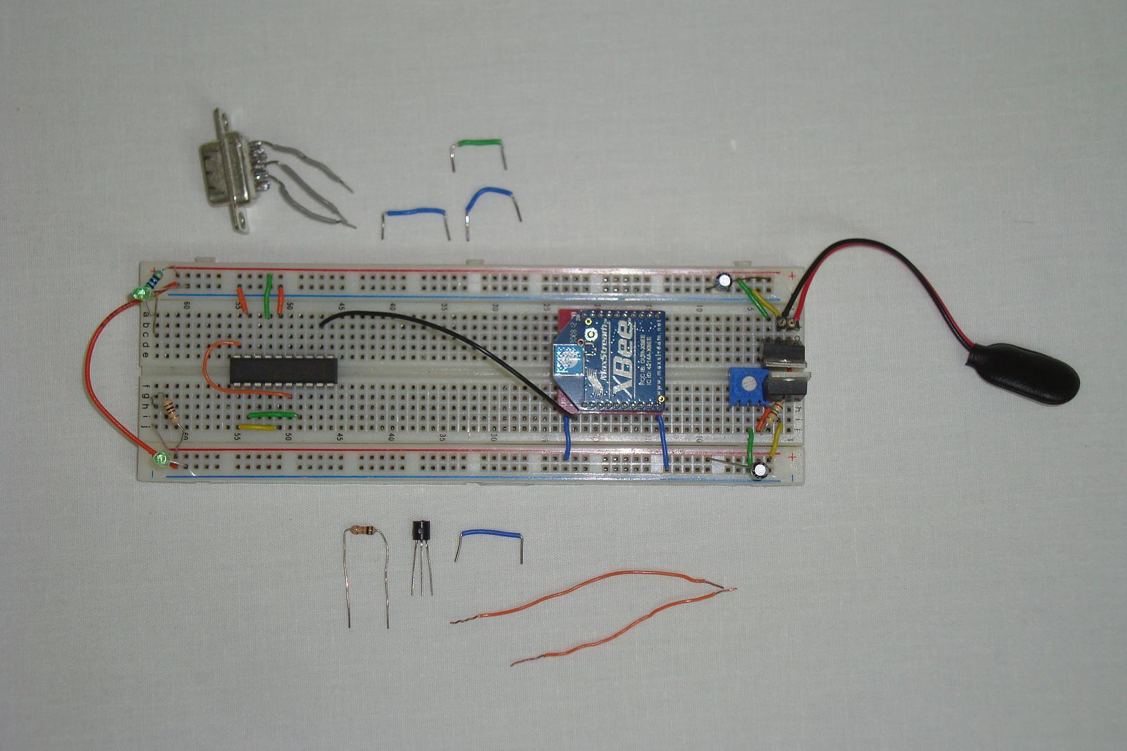
·Now, the MAX233a is added and connected to power, ground and the XBee.
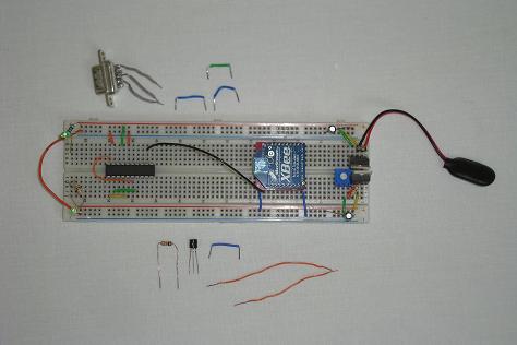
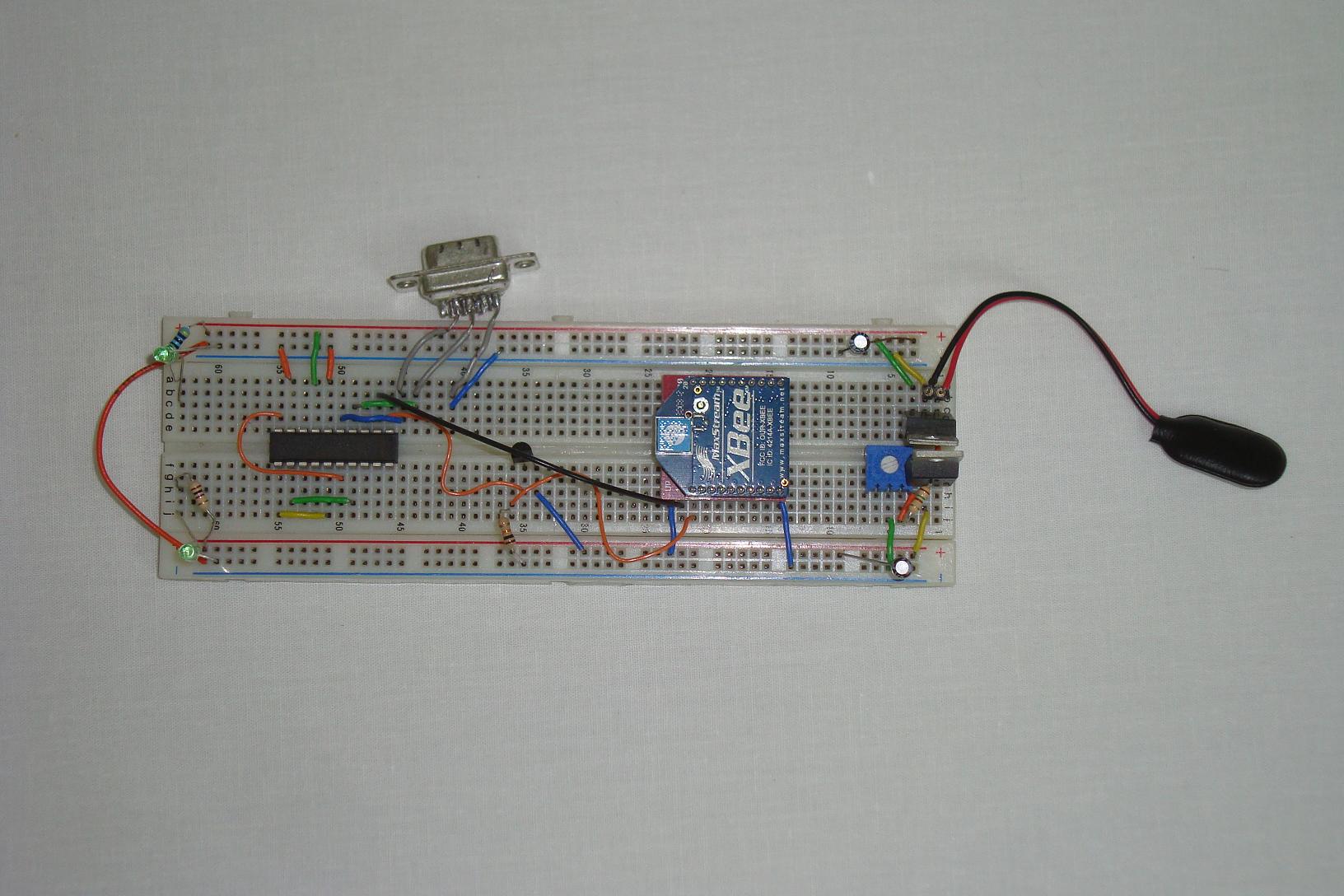
·Finally, the level shifter and 9 pin connector are connected to the MAX233a.
Building The Simple Circuit
This smaller XBee receiver circuit just involves connecting a XBee up to a power supply.
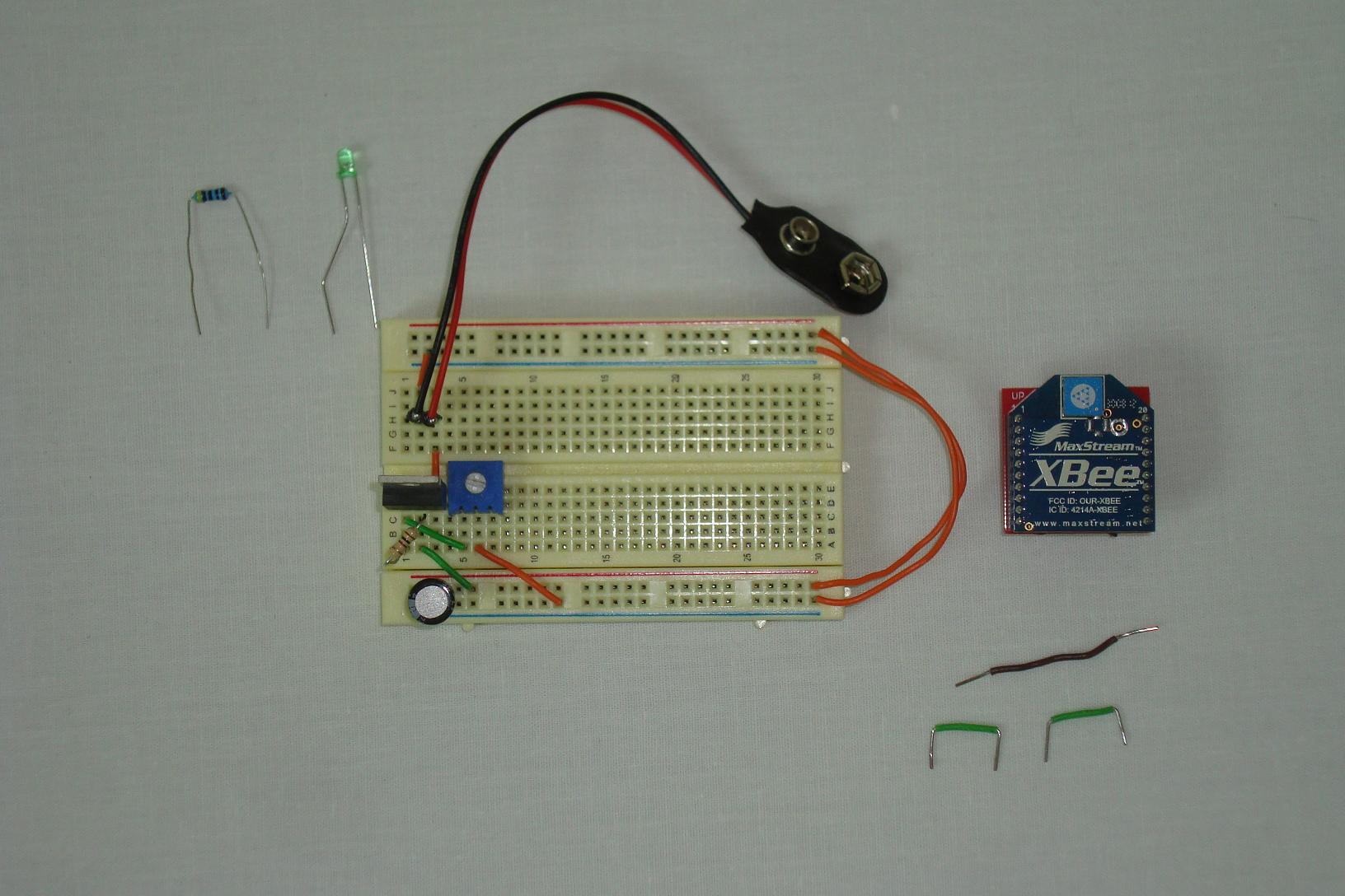
·First the LM317 power regulator is connected.
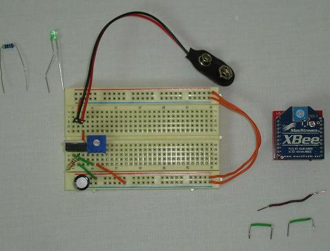
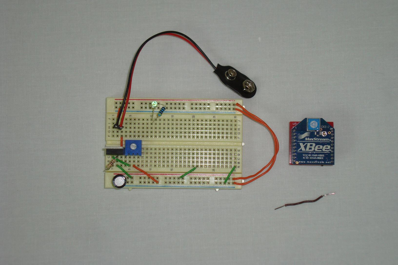
·The Power LED is added next, along with XBee power connections.
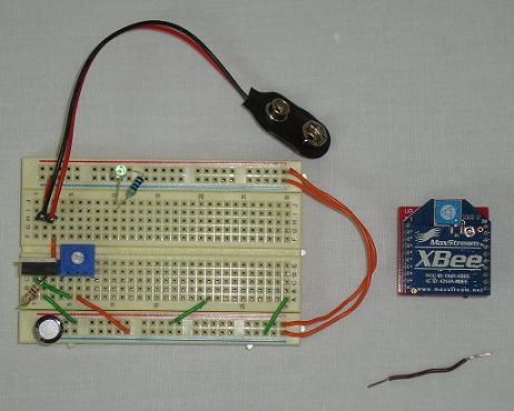
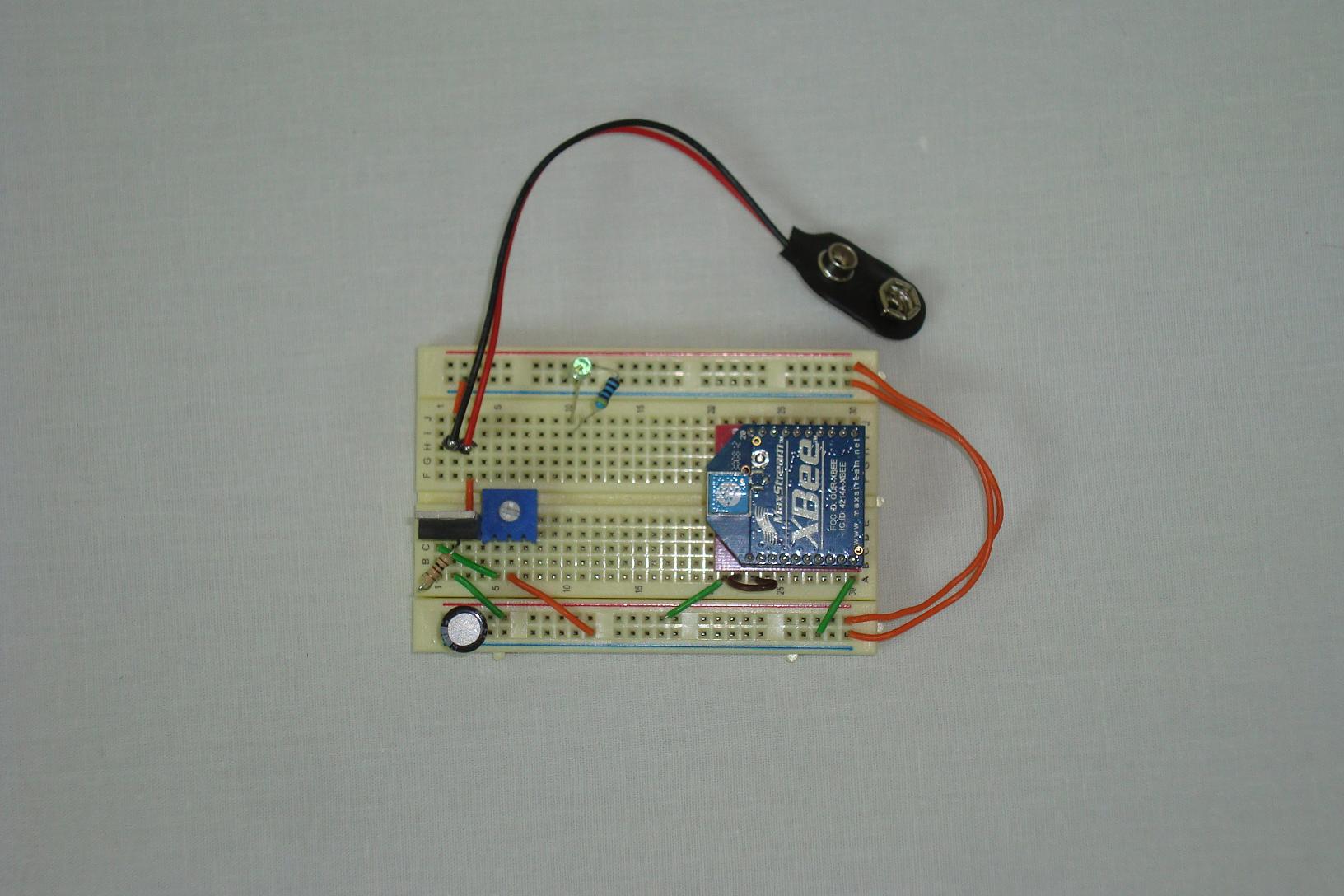
·Finally, the XBee Module is Connected the circuit with the loopback.
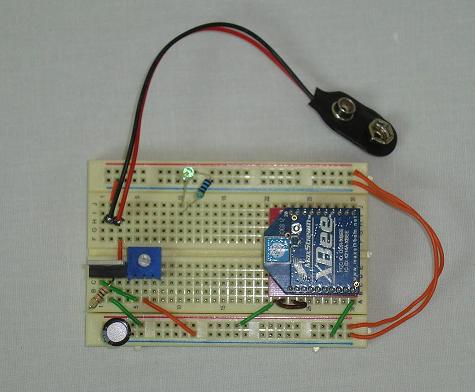
·Both circuits have been built and we're ready to start configuring!
This hardware section will show you how I built both circuits. First the main circuit that we will connect to a PC and then the super simple circuit that we'll use for the dual XBee range test..
Building The Complex Circuit
Get your parts together and follow the schematic. Each picture below will show how I connected the circuit together, in sections.
·First the +5v//+3.3v power regulator and power LEDs are added.

·Next, the XBee is added and connected to +3.3v power and ground.
·Now, the MAX233a is added and connected to power, ground and the XBee.
·Finally, the level shifter and 9 pin connector are connected to the MAX233a.
Building The Simple Circuit
This smaller XBee receiver circuit just involves connecting a XBee up to a power supply.

·First the LM317 power regulator is connected.
·The Power LED is added next, along with XBee power connections.
·Finally, the XBee Module is Connected the circuit with the loopback.
·Both circuits have been built and we're ready to start configuring!