Serial Communication Signals
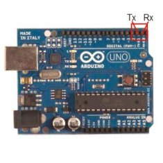
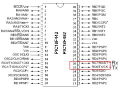
Each microcontroller, the PIC and the AVR (Arduino's micro) has a dedicated serial module in hardware. It's mostly just a super fancy digital shift register. If you look below you can see where to find the Tx (output) and Rx (input) pins on each of these devices. One common problem with connecting serial devices together is that people wire the Tx pin to Tx and Rx to Rx. Don't do that!..instead: always remember that Tx connects to Rx and Rx connects to Tx. This will save you a considerable amount of headaches.
Understanding the theory of RS232 serial communication, means looking down deep into the actual signals being transmitted. I hooked up an oscilloscope to capture two characters being transmitted, 1 and 5. A standard single transmission of RS232 serial communication will contain a start bit, 8 bits of information and a stop bit. Since there's only 8 bits of information, a system was invented called ASCII which is short for ~> The American Standard Code for Information Interchange.
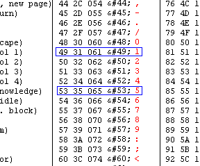
The table seen above encodes every bit of information necessary for transferring standard english communication, grammar and formatting. Specifically we are interested in the encoding for numbers '1' and '5'.
Example #1: Sending '5' via RS232 Serial Communication
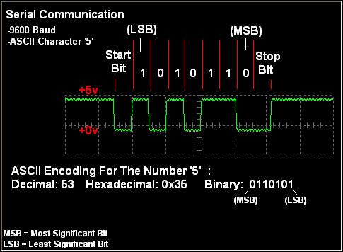
When you want to send the character '5' over serial communcation, each bit of that encoded character is sent one at a time, starting with the 'least significant bit' up to the 'most significant bit'. The picture above illustrates this process:
Example #2: Sending '1' via RS232 Serial Communication
When you want to send the character '1' over serial communcation, each bit of that encoded character is sent one at a time, starting with the 'least significant bit' up to the 'most significant bit'. The picture above illustrates this process:
It is important to understand at this level what is happening, that way if the Serial port on the receiver (PIC) or the sender (Laptop) is not working properly, we know what exactly should be happening at the lowest level. Ideally, we should never have to debug at this low of a level, but sometimes things just go wrong and we have to.
Each microcontroller, the PIC and the AVR (Arduino's micro) has a dedicated serial module in hardware. It's mostly just a super fancy digital shift register. If you look below you can see where to find the Tx (output) and Rx (input) pins on each of these devices. One common problem with connecting serial devices together is that people wire the Tx pin to Tx and Rx to Rx. Don't do that!..instead: always remember that Tx connects to Rx and Rx connects to Tx. This will save you a considerable amount of headaches.

Understanding the theory of RS232 serial communication, means looking down deep into the actual signals being transmitted. I hooked up an oscilloscope to capture two characters being transmitted, 1 and 5. A standard single transmission of RS232 serial communication will contain a start bit, 8 bits of information and a stop bit. Since there's only 8 bits of information, a system was invented called ASCII which is short for ~> The American Standard Code for Information Interchange.

The table seen above encodes every bit of information necessary for transferring standard english communication, grammar and formatting. Specifically we are interested in the encoding for numbers '1' and '5'.
Example #1: Sending '5' via RS232 Serial Communication
When you want to send the character '5' over serial communcation, each bit of that encoded character is sent one at a time, starting with the 'least significant bit' up to the 'most significant bit'. The picture above illustrates this process:
- [1] Send Start Bit (+5v ~> +0v)
- [2] Send 8 bit encoded character, LSB first
- [3] Send Stop Bit (+0v)
- [4] Finished Transmission (+0v ~> +5v)
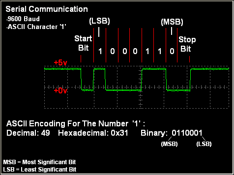
Example #2: Sending '1' via RS232 Serial Communication
When you want to send the character '1' over serial communcation, each bit of that encoded character is sent one at a time, starting with the 'least significant bit' up to the 'most significant bit'. The picture above illustrates this process:
- [1] Send Start Bit (+5v ~> +0v)
- [2] Send 8 bit encoded character, LSB first
- [3] Send Stop Bit (+0v)
- [4] Finished Transmission (+0v ~> +5v)
It is important to understand at this level what is happening, that way if the Serial port on the receiver (PIC) or the sender (Laptop) is not working properly, we know what exactly should be happening at the lowest level. Ideally, we should never have to debug at this low of a level, but sometimes things just go wrong and we have to.