Hardware Transmitter Design
Lucky for us the hardware design and construction process is only 4 steps. Scroll down to see how it starts out!
Putting Everything Together
Double check you have all the parts seen in the schematic and get ready to start building! The first step is always gathering the parts together so you can start building; below you can see all the parts.
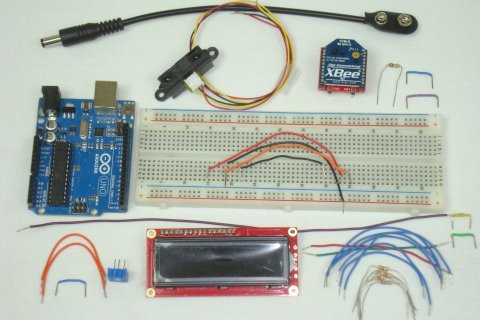
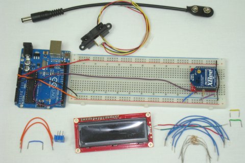
The first connections are connecting the +5v power to one side of the breadboard, +3.3v to the other side and also ground. Then the XBee module was connected to the +3.3v power, ground and to the Arduino's Rx digital pin 0.
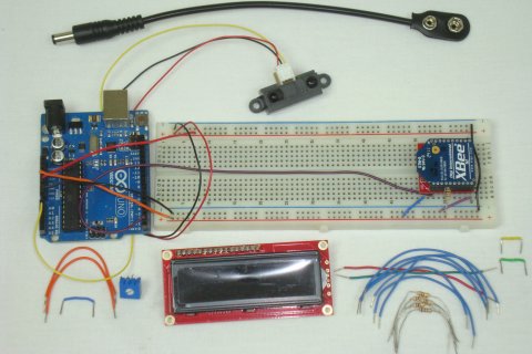
Next, the proximity sensor is connected to the +5v power, ground and its Voutput pin goes to Arduino's A0 analog pin 0.
The last step is connecting the 16x2 LCD to the Arduino. Follow the schematic and get it all wired up.
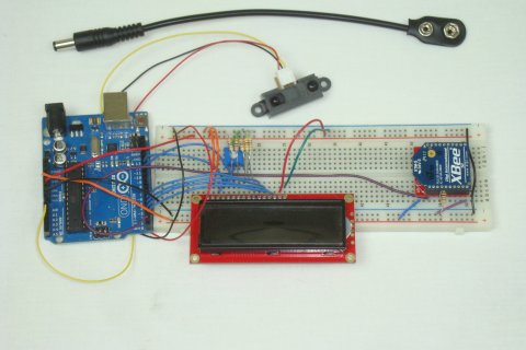
That's it, the transmitter is built! Let's take a look at how to build the PIC receiver system.
Lucky for us the hardware design and construction process is only 4 steps. Scroll down to see how it starts out!
Putting Everything Together
Double check you have all the parts seen in the schematic and get ready to start building! The first step is always gathering the parts together so you can start building; below you can see all the parts.
The first connections are connecting the +5v power to one side of the breadboard, +3.3v to the other side and also ground. Then the XBee module was connected to the +3.3v power, ground and to the Arduino's Rx digital pin 0.
Next, the proximity sensor is connected to the +5v power, ground and its Voutput pin goes to Arduino's A0 analog pin 0.
The last step is connecting the 16x2 LCD to the Arduino. Follow the schematic and get it all wired up.
That's it, the transmitter is built! Let's take a look at how to build the PIC receiver system.