Transmitter Schematic Overview
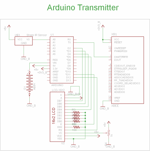
The schematic for the transmitter in this project has 4 main parts, the Arduino UNO, the sharp IR distance sensor, the XBee Wireless Modules and the 16x2 LCD. You can see how these parts are connected together to build the system we want in the schematic below:
View Full Schematic
Schematic Specifics
Power Supply
The arduino has on-board power regulators so we don't have to do anything special besides plug in a standard DC power jack, which will be regulated to +5v and +3.3v.
IR Distance Sensor Input
The IR Proximity Sensor has a 3 pin connector that is super simple, Vsupply, Gnd, Vout. Vsupply is connected to +5v power and Gnd to Ground. Vout will be connecting to pin AN0 of the Arduino, this is an analog-to-digital converter pin.
XBee Wireless Module
This module will be used for transmitting the command from the Arduino UNO to the PIC receiver system. XBee modules run off of +3.3v so its important not to use a +5v system here!
16x2 LCD
This is a standard 16x2 LCD display that runs off of the hitachi hd44780 command set. It will be used to display output to us so that we know the wireless communication is working and so that we can know what motor speed we're currently at.
Receiver Schematic Overview
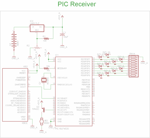
The schematic for receiver part of this project has 4 main parts, the 18F4520 microcontroller, the XBee Maxstream, the power transistor and the LED bar. You can see how these parts are connected together to build the system we want in the schematic below:
View Full Schematic
Schematic Specifics
Power Supply
To make things simple, we'll use a LM317 variable regulator to supply the power for this entire project. We will configure it to output +3.3v with a resistor + trimpot configuration.
XBee Wireless Module
This is the second XBee module that will be used to passing the received command to the PIC 18LF4520 for processing. Again, we're using a +3.3v PIC because the XBee modules cannot operate at +5v power!
Motor Control Circuit
The TIP42 power transistor allows the motor to be turned off or on. The base pin of the TIP42 is connected to the PIC microcontroller's CCP1 pin, which is a PWM output pin from the PIC. PWM will be used to drive the motor at different speeds as we discussed in the theory section.
LED Bar Output
To give a visual read-out of the current status and speed level (level 0 to 8, 0 motor is off, 8 motor is full speed!) we'll use an LED Bar connected to the PIC microcontroller's PORTD. This port has 8 digital I/O pins which will each drive a single LED, on the LED Bar.
The schematic for the transmitter in this project has 4 main parts, the Arduino UNO, the sharp IR distance sensor, the XBee Wireless Modules and the 16x2 LCD. You can see how these parts are connected together to build the system we want in the schematic below:
View Full Schematic
Schematic Specifics
Power Supply
The arduino has on-board power regulators so we don't have to do anything special besides plug in a standard DC power jack, which will be regulated to +5v and +3.3v.
IR Distance Sensor Input
The IR Proximity Sensor has a 3 pin connector that is super simple, Vsupply, Gnd, Vout. Vsupply is connected to +5v power and Gnd to Ground. Vout will be connecting to pin AN0 of the Arduino, this is an analog-to-digital converter pin.
XBee Wireless Module
This module will be used for transmitting the command from the Arduino UNO to the PIC receiver system. XBee modules run off of +3.3v so its important not to use a +5v system here!
16x2 LCD
This is a standard 16x2 LCD display that runs off of the hitachi hd44780 command set. It will be used to display output to us so that we know the wireless communication is working and so that we can know what motor speed we're currently at.
Receiver Schematic Overview
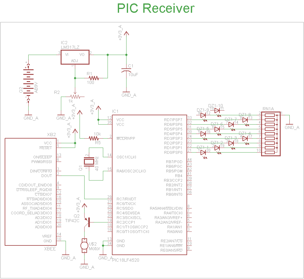
The schematic for receiver part of this project has 4 main parts, the 18F4520 microcontroller, the XBee Maxstream, the power transistor and the LED bar. You can see how these parts are connected together to build the system we want in the schematic below:
View Full Schematic
Schematic Specifics
Power Supply
To make things simple, we'll use a LM317 variable regulator to supply the power for this entire project. We will configure it to output +3.3v with a resistor + trimpot configuration.
XBee Wireless Module
This is the second XBee module that will be used to passing the received command to the PIC 18LF4520 for processing. Again, we're using a +3.3v PIC because the XBee modules cannot operate at +5v power!
Motor Control Circuit
The TIP42 power transistor allows the motor to be turned off or on. The base pin of the TIP42 is connected to the PIC microcontroller's CCP1 pin, which is a PWM output pin from the PIC. PWM will be used to drive the motor at different speeds as we discussed in the theory section.
LED Bar Output
To give a visual read-out of the current status and speed level (level 0 to 8, 0 motor is off, 8 motor is full speed!) we'll use an LED Bar connected to the PIC microcontroller's PORTD. This port has 8 digital I/O pins which will each drive a single LED, on the LED Bar.