TIP42 Motor Control
Now, we'll take a look at how the motor will be controlled through the power transistor; the tip42. This power transistor will receive an input pulse from the microcontroller called PWM, pulse with modulation. Since the TIP42 is a PNP type transistor, any time the base pin is +0v, the transistor will be turned on and thus the motor will be turned on. To see what PWM looks like, take a look below:
PWM Explained - Pulse With Modulation

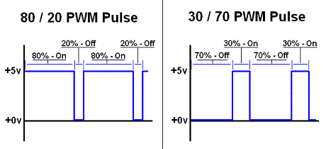
The two images above show you two different PWM signals. The first signal is "on" 80% of the time. That means it is at +5v for 80% of the period of the signal. This is a weak signal and it would make the motor for this project run very slowly, if at all.
The second image shows you a signal similar to the first, but it is only on 30% of the time. It is at +0v for 70% of the period of the signal. Since this PWM signal is in an 'off' state for the majority of the time, it would make the motor for this project run much fast than the first PWM.
This might seem backwards with all the 'on' and 'off' being switched, but that is due to the fact that we're using a PNP transistor. If you want you could use an NPN transistor and everything would be opposite and therefore a little more normal.
Now, we'll take a look at how the motor will be controlled through the power transistor; the tip42. This power transistor will receive an input pulse from the microcontroller called PWM, pulse with modulation. Since the TIP42 is a PNP type transistor, any time the base pin is +0v, the transistor will be turned on and thus the motor will be turned on. To see what PWM looks like, take a look below:

The two images above show you two different PWM signals. The first signal is "on" 80% of the time. That means it is at +5v for 80% of the period of the signal. This is a weak signal and it would make the motor for this project run very slowly, if at all.
The second image shows you a signal similar to the first, but it is only on 30% of the time. It is at +0v for 70% of the period of the signal. Since this PWM signal is in an 'off' state for the majority of the time, it would make the motor for this project run much fast than the first PWM.
This might seem backwards with all the 'on' and 'off' being switched, but that is due to the fact that we're using a PNP transistor. If you want you could use an NPN transistor and everything would be opposite and therefore a little more normal.