An Overview Of The Wireless Sensor Motor Control
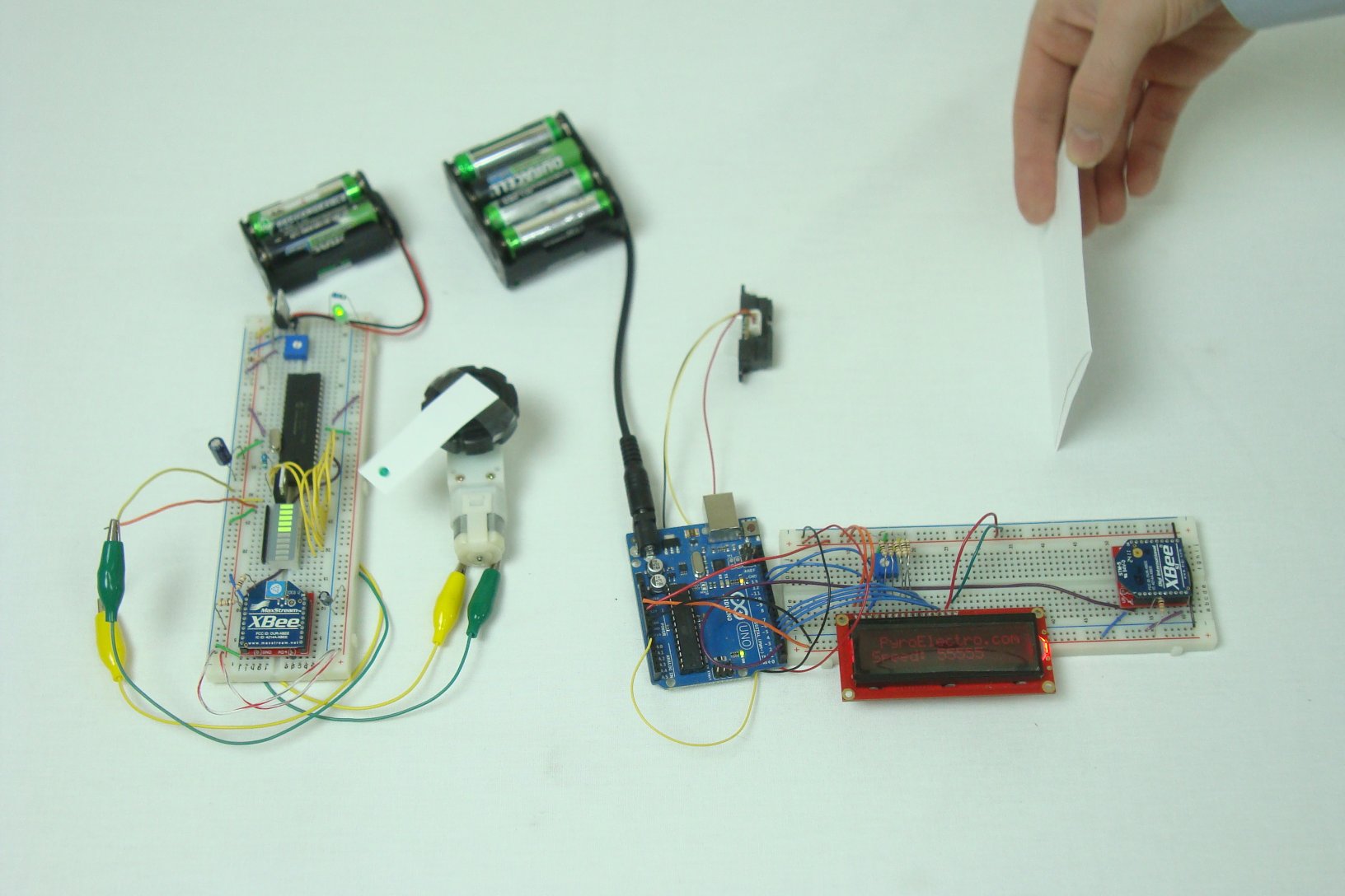
Each part of this system, the transmitter and the receiver had two main components. The transmitter used a 16x2 LCD and a sharp IR proximity sensor, the receiver had an LED bar and a motor control circuit. Each of these external components were used to build the wirelessly controlled system that you just learned about. As a system it seemed fairly robust and very responsive to quick and sudden changes. There's always room for improvement, but overall what we saw in the demonstration video was a fluid system that worked well.

What To Do Now
This article demonstrates one of many possible projects that can be done with the special parts like wireless XBee modules or infrared proximity sensors. There are many other directions you can take, like controlling specifics robotics. All systems will be reactive based off of input, and the IR distance sensor we used in this article is a great starting point to expand upon. Have fun with it!
Conclusion
The main goal of this article was to make a working transmitter and receiver system that took input, transmitted it and reacted at the receiver side. In that goal we were successful as we demonstrated in the data & observations section. The system worked consistently, but due to its simplicity left a wide window of ways that it could be improved. So go make something better!
If you have any further questions, I implore you...don't be shy, take a look at the forums or ask a question there. I check them out regularly and love getting comments & questions.
Each part of this system, the transmitter and the receiver had two main components. The transmitter used a 16x2 LCD and a sharp IR proximity sensor, the receiver had an LED bar and a motor control circuit. Each of these external components were used to build the wirelessly controlled system that you just learned about. As a system it seemed fairly robust and very responsive to quick and sudden changes. There's always room for improvement, but overall what we saw in the demonstration video was a fluid system that worked well.
What To Do Now
This article demonstrates one of many possible projects that can be done with the special parts like wireless XBee modules or infrared proximity sensors. There are many other directions you can take, like controlling specifics robotics. All systems will be reactive based off of input, and the IR distance sensor we used in this article is a great starting point to expand upon. Have fun with it!
Conclusion
The main goal of this article was to make a working transmitter and receiver system that took input, transmitted it and reacted at the receiver side. In that goal we were successful as we demonstrated in the data & observations section. The system worked consistently, but due to its simplicity left a wide window of ways that it could be improved. So go make something better!
If you have any further questions, I implore you...don't be shy, take a look at the forums or ask a question there. I check them out regularly and love getting comments & questions.