Schematic Overview
The RF modules used in this schematic are very simple, with only a few extra pins required for power, ground and data. The main parts used in this schematic are the RF transmitter module, RF receiver module, 18F452 and 18F4520. You can see them below, as well as the specific circuits described in more detail.
Transmitter Schematic 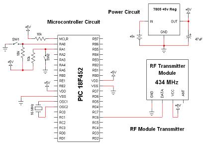
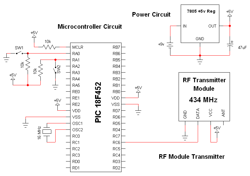
View Full Schematic
Receiver Schematic 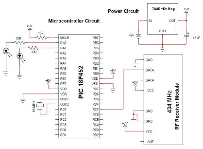
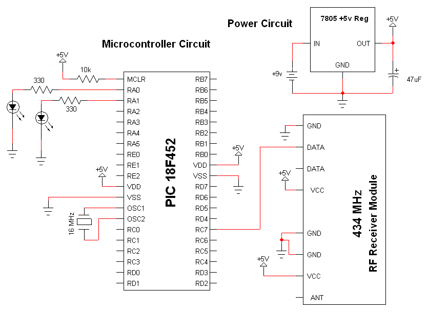
View Full Schematic
Schematic Specifics
Power Circuits
Since there are two seperate circuits, both need to have a power supply circuit. The power supply in both circuits is identical, a LM7805 takes battery input and regulates it down to +5v. The DC filtering capacitor cleans up any noise off the +5v output.
Microcontroller Circuits
The only difference for this part of the circuit is that the receiver uses the RX pin (PORTC 7) on the PIC and the transmitter uses the TX pin (PORTC 6) on the PIC. Both of these data lines connect to the data pin on the transmitter or receiver module.
Wireless Module Circuits
These two modules are in charge of passing the data from one link to the other without adding too much error. We'll see later in the theory section how the receiver module can be altered to help correct distortion.
The RF modules used in this schematic are very simple, with only a few extra pins required for power, ground and data. The main parts used in this schematic are the RF transmitter module, RF receiver module, 18F452 and 18F4520. You can see them below, as well as the specific circuits described in more detail.
View Full Schematic
View Full Schematic
Schematic Specifics
Power Circuits
Since there are two seperate circuits, both need to have a power supply circuit. The power supply in both circuits is identical, a LM7805 takes battery input and regulates it down to +5v. The DC filtering capacitor cleans up any noise off the +5v output.
Microcontroller Circuits
The only difference for this part of the circuit is that the receiver uses the RX pin (PORTC 7) on the PIC and the transmitter uses the TX pin (PORTC 6) on the PIC. Both of these data lines connect to the data pin on the transmitter or receiver module.
Wireless Module Circuits
These two modules are in charge of passing the data from one link to the other without adding too much error. We'll see later in the theory section how the receiver module can be altered to help correct distortion.