Hardware Design
Since this tutorial uses breadboards, there is not much design work to be done, just assembling the schematic on the two breadboards. So below I'll go through the process of building the two circuits on the breadboards, step-by-step.
Building The Transmitter Circuit
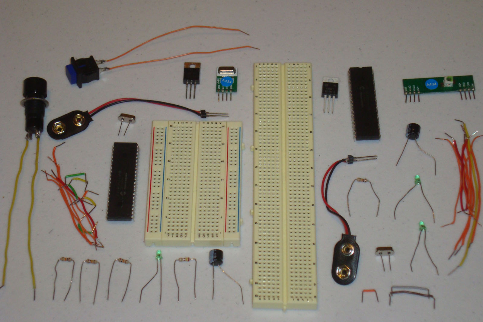
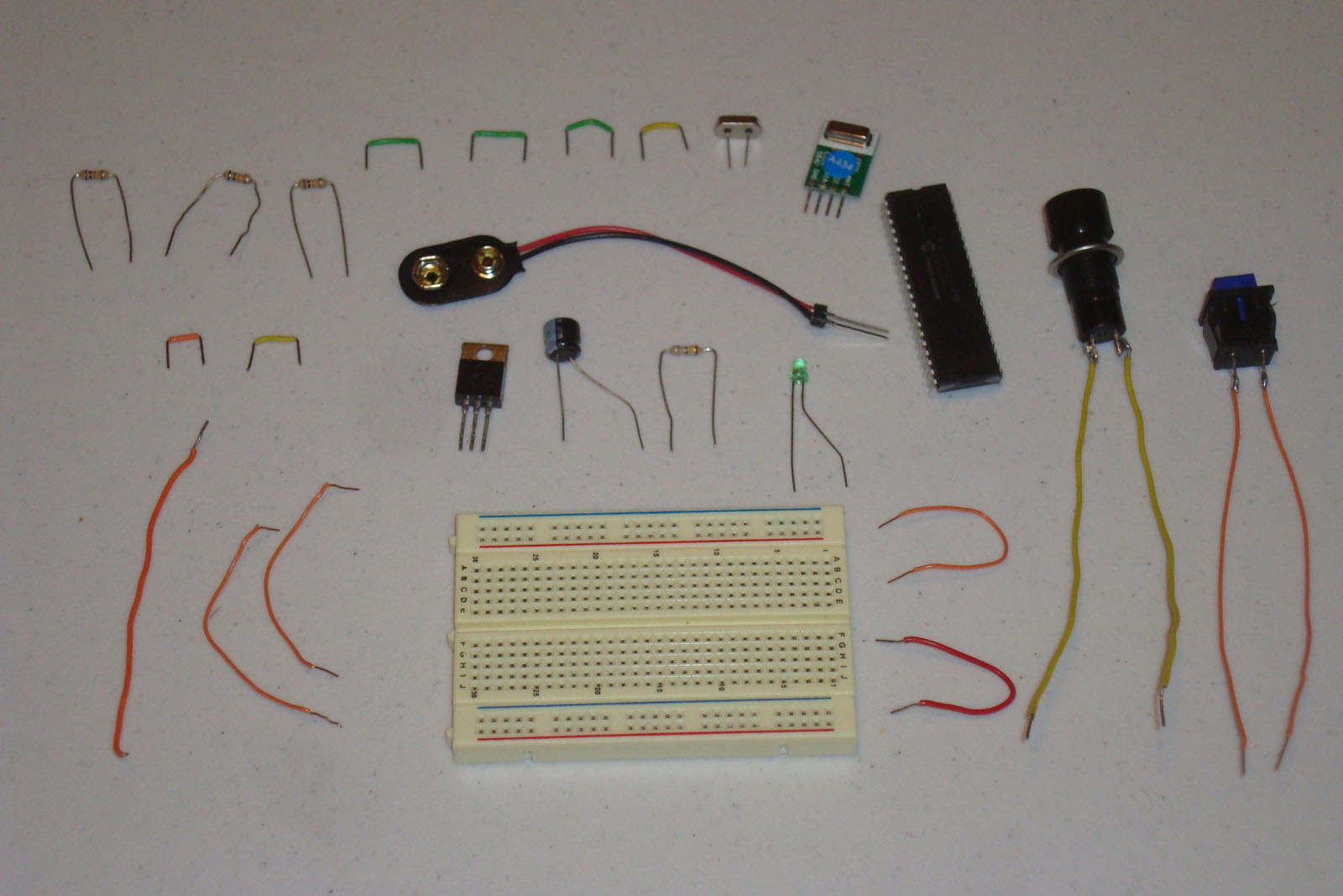
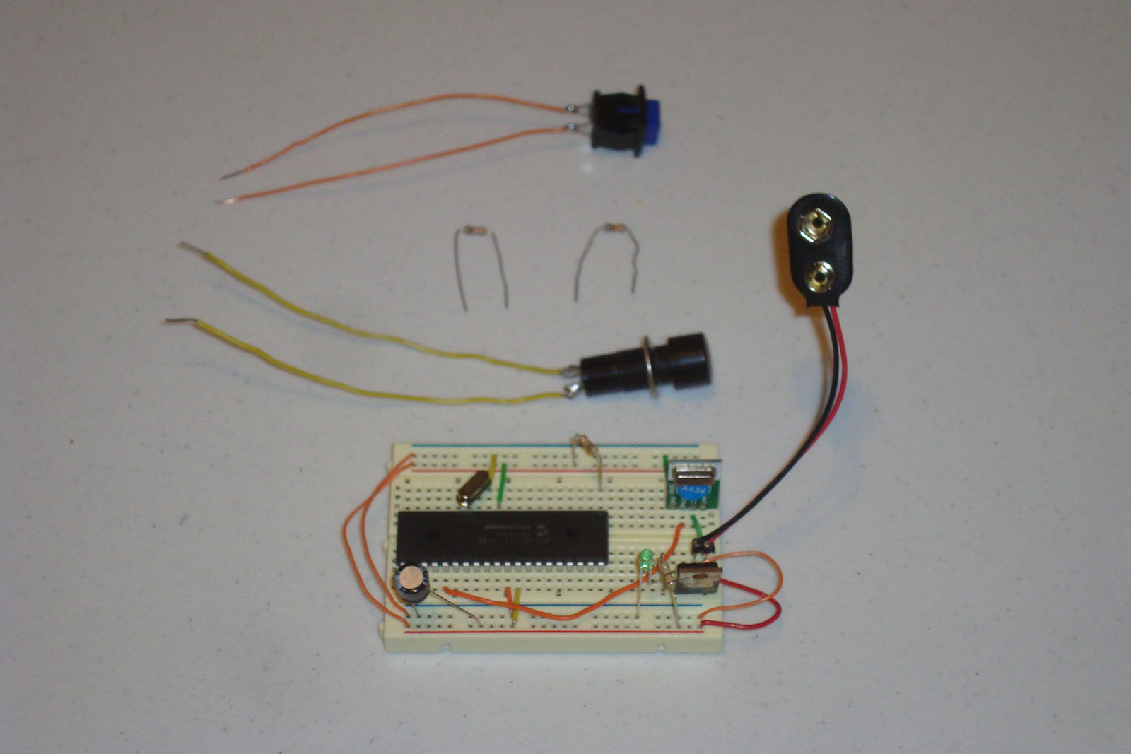
Gather all the parts for the two breadboards that need to be assembled, they are pictured below.
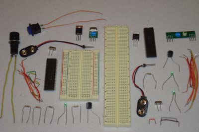
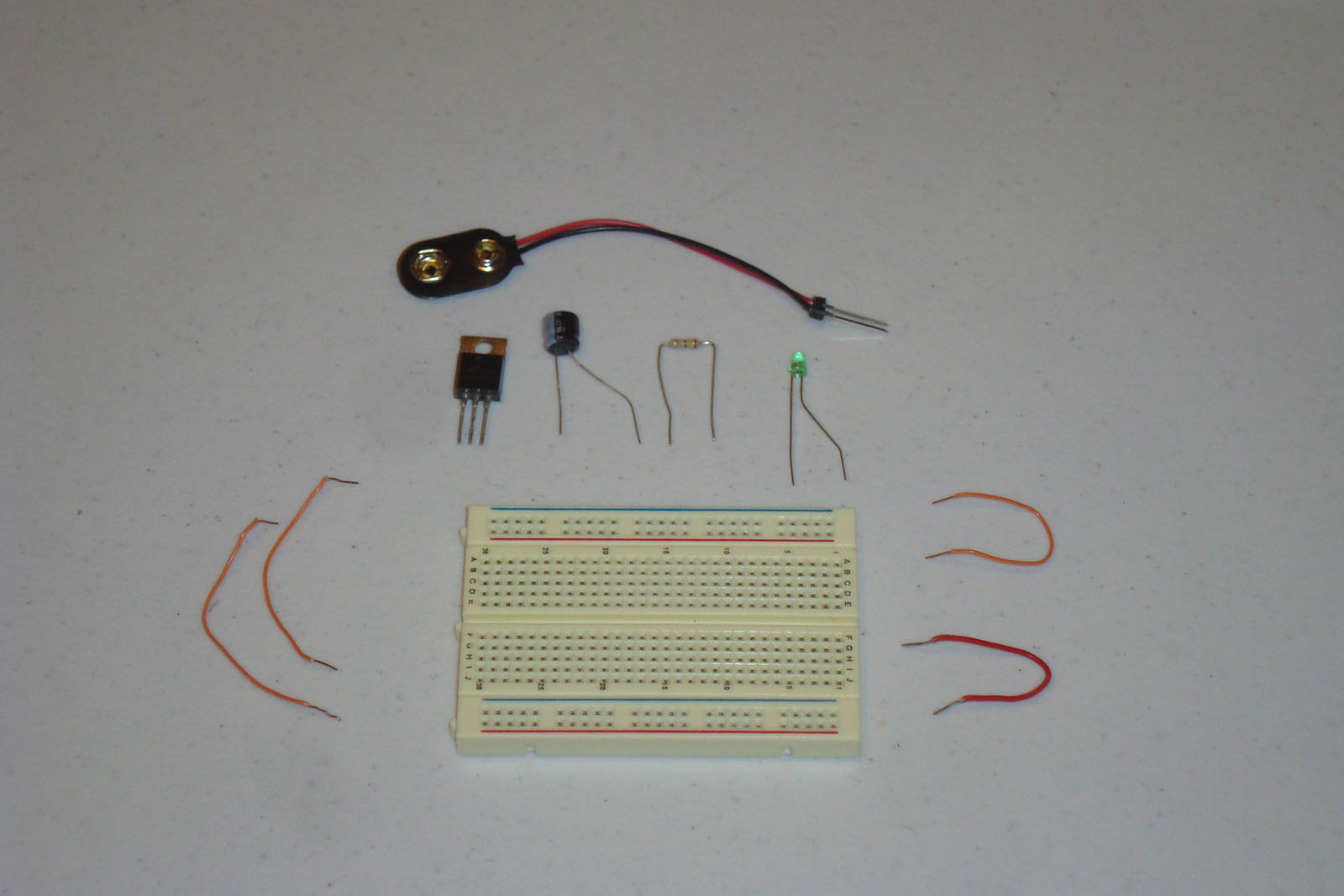
·First we'll start by building the transmitter circuit, so we'll only need those parts.
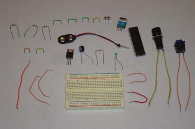
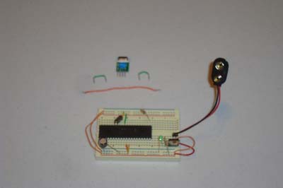
·The power circuit should be the first thing assembled.
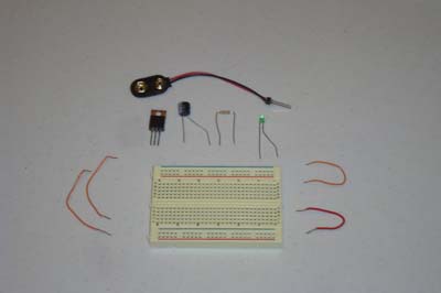
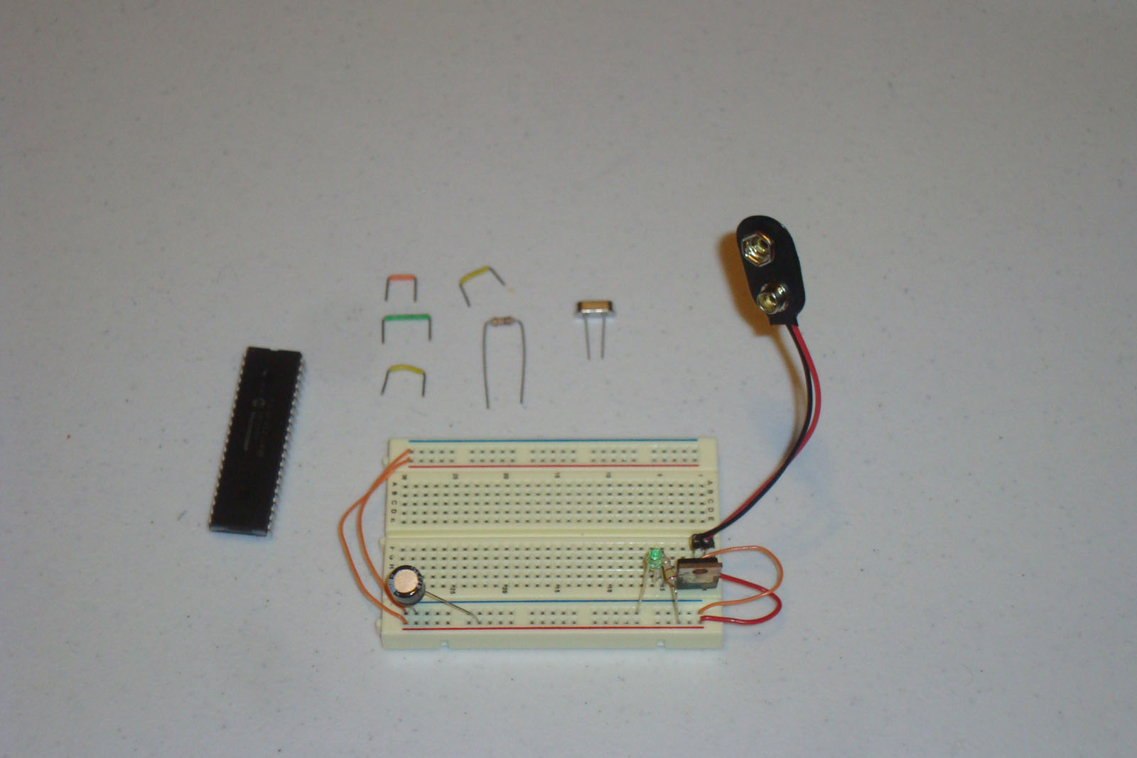
·Now add the microcontroller circuitry to the breadboard.
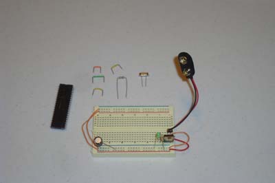
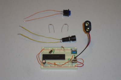
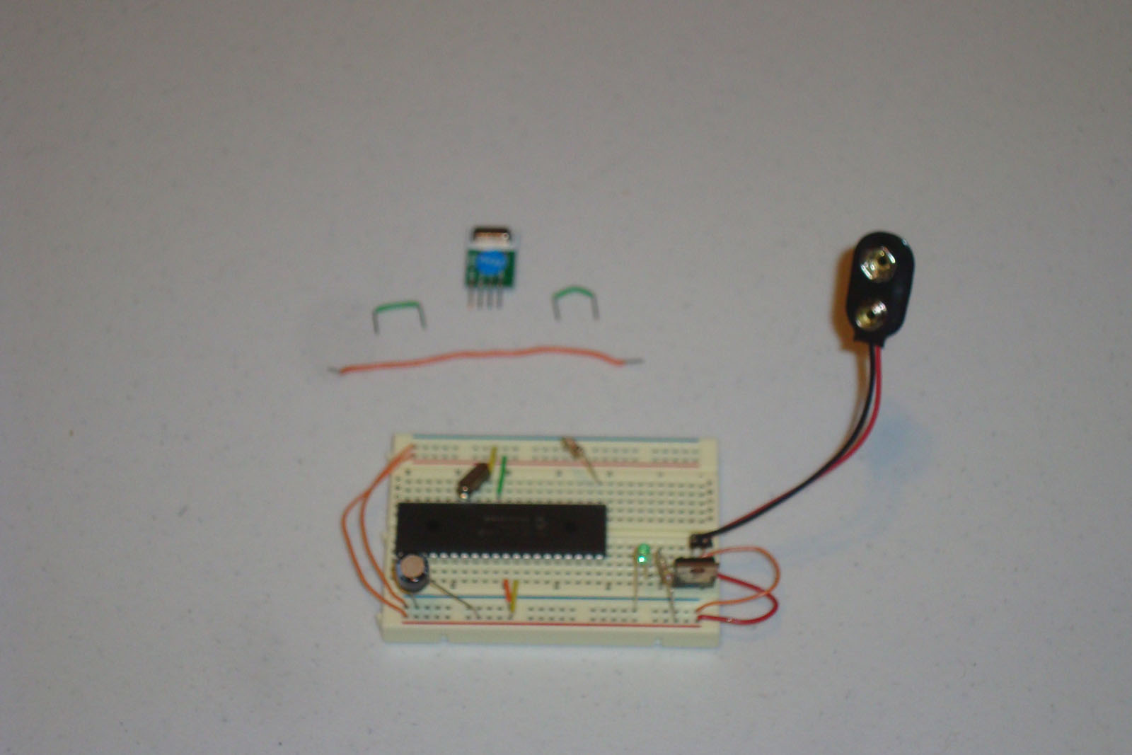
·The RF Transmitter Module is next, connect it to the PIC, Power and Ground.
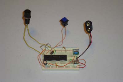
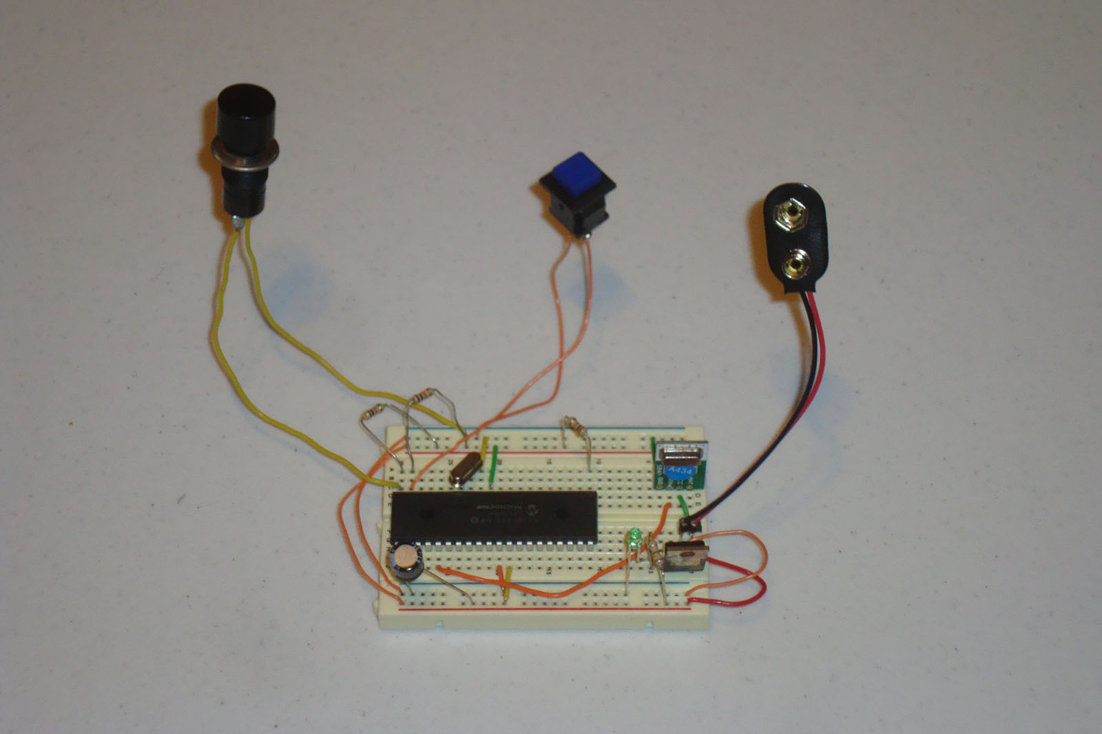
·Now, add the buttons to the circuit with pull-up resistors.
·The RF Transmitter hardware has been wired up and is complete.
·Next, the RF Receiver hardware needs to be assembled.
Since this tutorial uses breadboards, there is not much design work to be done, just assembling the schematic on the two breadboards. So below I'll go through the process of building the two circuits on the breadboards, step-by-step.
Building The Transmitter Circuit
Gather all the parts for the two breadboards that need to be assembled, they are pictured below.
·First we'll start by building the transmitter circuit, so we'll only need those parts.
·The power circuit should be the first thing assembled.
·Now add the microcontroller circuitry to the breadboard.
·The RF Transmitter Module is next, connect it to the PIC, Power and Ground.
·Now, add the buttons to the circuit with pull-up resistors.
·The RF Transmitter hardware has been wired up and is complete.
·Next, the RF Receiver hardware needs to be assembled.