Project Info
Author: Chris
Difficulty: Medium
Time Invested: 3 Hours
Prerequisites:
Take a look at the above
tutorials before continuing
to read this tutorial.
Author: Chris
Difficulty: Medium
Time Invested: 3 Hours
Prerequisites:
Take a look at the above
tutorials before continuing
to read this tutorial.
Understanding how to build proper control circuit for the stepper motor is vital. Knowing how much current will be drawn by the motor and the planned system voltage is essential. Throughout this tutorial my system voltage will be 12v for the motors and current draw will not exceed 300mA. Stepper motors can draw a lot of current so check the specs on what you're using.

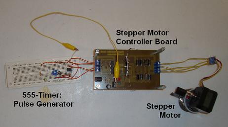
Purpose & Overview of this project
The goal of this project is to build a board specifically for controlling a 2 coil stepper motor. The board should have 4 terminal block ports for the 4 stepper motor wires, and 4 input ports for the L297 controller.
The board should be able to reliably control the steps that the motor takes. Each clock pulse into the circuit will put the motor through exactly 1 stepping cycle.