Schematic Overview
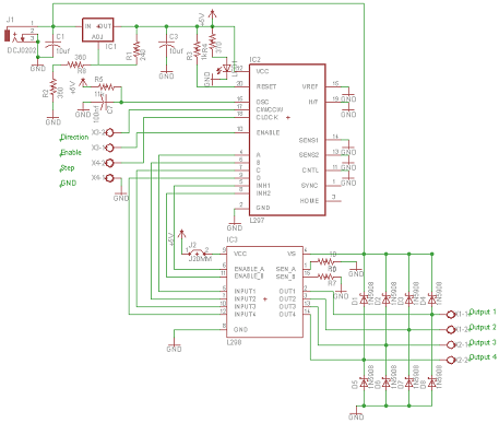
The schematic for the board can be seen below. The three main elements of the board are (1) the power input and voltage regulation, (2) the L297 input and outputs and (3) the L298 stepper motor control circuit.
View Full Schematic
Schematic Specifics
Voltage Regulation
While the motor is powered by a raw +12v input, there is a voltage regulator circuit for +5v going to the L297. The LM317 uses a voltage divider 240Ω and 720Ω on its output and adjust pins to create this +5v output.
L297 Control Signals
The L297 has 4 inputs supplied by the user, a ground, step input (clock), direction and enable. From these inputs the L297 decides what outputs should be given to the L298 in order to control the stepper motor properly.
L298 Motor Control
The L298 will constantly be supplying current to the stepper motor unless you add additional sensing circuitry, so make sure you don't forget the 10Ω resistors off of pins 1 & 15, the sense pins. This limits the current to 300mA and means out L298 won't get hot enough to burn finger tips. If you want to see what I mean, connect pins 1 and 15 directly to ground and the L298 will burn up.
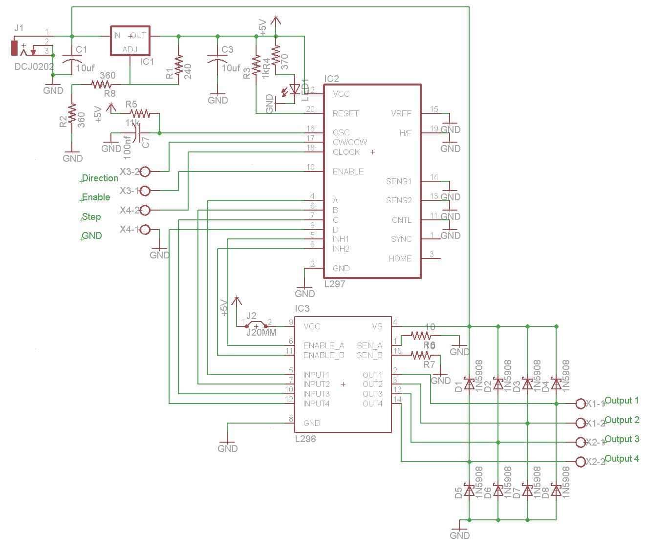