Now we can start the building. First to the right you can download the project schematic, board layout, parts list and pdf of the board layout. After you have the layout printed out, the first step is to get your copper clad board out, iron hot and use the toner transfer method to get the ink onto the pcb.
Building The Circuit
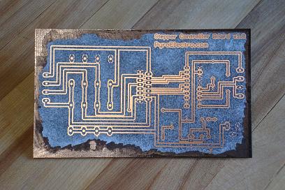
The tone should transfer onto the copper clad pc board and look similar to below:
·Use a black sharpie or touch-up pen to fix anything that didn't transfer, then give the board a ferric chloride bath to eat the excess copper.
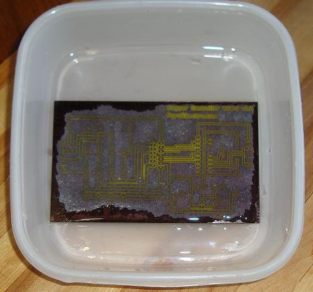
·The copper should be gone in only a few minutes leaving copper under the toner still in tact. Wash the board of with some water and then go at it with a sponge to get the leftover tone off the board.
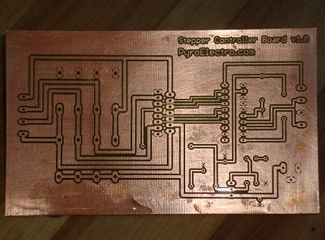
·After some intense scrubbing you'll see a nice clean board that is ready to be drilled and soldered.
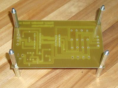
·After you have drilled all the holes into the board, you can solder the parts into it. I usually don't bother tinning the board. The copper loves the solder as long as its not too dirty. Also, put some standoffs on your board, it'll make soldering easier!
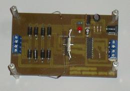
·Here's a top view of the finished board. I messed up while soldering and had to route the two 10ohm sense resistors to the ground plane.
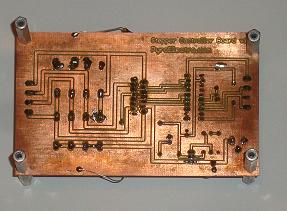
·A bottom view of the finished board. All the parts have been soldered in and now its time to test this baby out!