The Theory
Here's a crash course in stepper motor control theory. A stepper motor has two or more coils and using these coils in a specific order (charging and discharging) we can get the motor to move. Not only can we get it to move but we can control the speed, force and many other factors that give desired precise control. Below is a picture that illustrates a four coil motor with coils being charged one at a time in a 'uni-polar' way.
Unipolar Stepper Motor
Very often stepper motors will come with many, many wire so that you can configure it exactly how you like. A standard stepper motor with 2 coils should have 4 wires. If there's a center tap on the coil there will be 6 wires. Be sure to have the datasheet of your stepper motor handy so you can pick out which color wire goes to which side of the coil inside the stepper motor. This is handy when you are wiring the stepper motor because if you wire it incorrectly the motor will act 'funky', probably because the coils are fighting each other, trying to move the motor in oppsite directions.
The Stepper Motor Controller Board
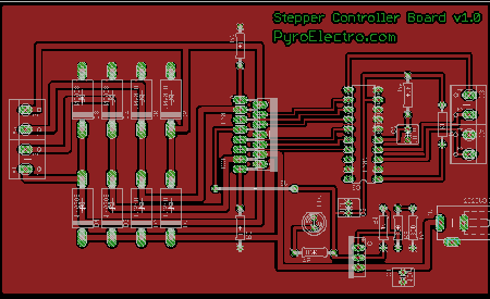
Above is the final picture of the board drawn out in eagle board view. On the right hand side you can see outlines of four terminal block inputs. These inputs go directly to the L297. If you follow the L297 to the L298 (in the middle of the board) you'll see 6 wires that connect the two devices together directly. These are the main control signals tell the L298 what to do and when. The left hand side of the board is basically just the big diodes and the stepper motor output. If all goes well (in theory and in practice) when a pulse from a 555 timer is applied to this board, a stepper motor should start running through steps and turning round and round.
Here's a crash course in stepper motor control theory. A stepper motor has two or more coils and using these coils in a specific order (charging and discharging) we can get the motor to move. Not only can we get it to move but we can control the speed, force and many other factors that give desired precise control. Below is a picture that illustrates a four coil motor with coils being charged one at a time in a 'uni-polar' way.
Very often stepper motors will come with many, many wire so that you can configure it exactly how you like. A standard stepper motor with 2 coils should have 4 wires. If there's a center tap on the coil there will be 6 wires. Be sure to have the datasheet of your stepper motor handy so you can pick out which color wire goes to which side of the coil inside the stepper motor. This is handy when you are wiring the stepper motor because if you wire it incorrectly the motor will act 'funky', probably because the coils are fighting each other, trying to move the motor in oppsite directions.
Above is the final picture of the board drawn out in eagle board view. On the right hand side you can see outlines of four terminal block inputs. These inputs go directly to the L297. If you follow the L297 to the L298 (in the middle of the board) you'll see 6 wires that connect the two devices together directly. These are the main control signals tell the L298 what to do and when. The left hand side of the board is basically just the big diodes and the stepper motor output. If all goes well (in theory and in practice) when a pulse from a 555 timer is applied to this board, a stepper motor should start running through steps and turning round and round.