Project Info
Author: Chris
Difficulty: Medium
Time Invested: 2 Hours
Prerequisites:
Take a look at the above
tutorials before continuing
to read this tutorial.
Author: Chris
Difficulty: Medium
Time Invested: 2 Hours
Prerequisites:
Take a look at the above
tutorials before continuing
to read this tutorial.
This tutorial will continue using the CPLD development board made previously and add some VGA hardware in order to make a 512 color VGA controller. The CPLD that we will use is an Altera EPM7128 which is widely available for purchase. It is also relatively old, but does the trick for this tutorial.

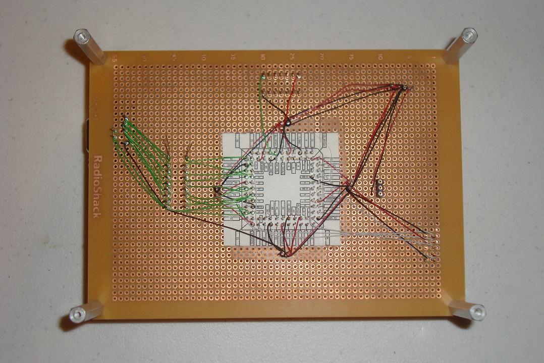
Purpose & Overview of this project
The purpose of this tutorial is to modify the CPLD development board so that it can output 512 colors to a VGA monitor. This will be done using a 9 resistor DAC (digital to analog converter) connected to 9 pins on the FPGA. A 25.175 MHz can oscillator will also be needed for the global clock input signal into the CPLD.
The language of choice to use with the CPLD and Altera's tools will be VHDL. Please be sure you're familiar with VHDL before continuing or at least take a look at the Introduction To VHDL tutorial. Since we're using an Altera FPGA, that means we will need to also use the Quartus II development enviornment.