The Theory
How does the VGA resistor DAC work? Well that's what the theory section is meant to answer! VGA color signals: Red, Green and Blue are all internally terminated through the monitor with a resistance of 75Ω which we can use to our advantage. If we add resistance to the output of any signal, a voltage divider will form decreasing the output voltage. Since VGA uses the analog voltage on the Red, Green and Blue color signals to denote color intensity, we now have a cheap and easy way to create lots of colors.
VGA Colors to Voltage Relationship
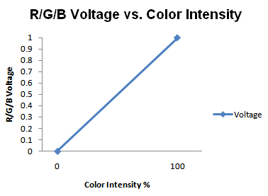
The VGA standard says that during active video display, the analog voltages on the R/G/B color signals correlates to their intensity. 1.0v is 100% color intensity and 0.0v is 0% intensity. This means if, for example, we want to be able to display 8 unique shades of Red, we will need to be able to create 8 unique voltages between 1.0v and 0.0v. So this means we need to choose some resistors to connect to the CPLD, so that we can create these analog voltages.
Choosing VGA Resistor DAC Values
Using a simulation tool called Pspice we can create a netlist (picture above) that does all the ohm's law calculations for us. After playing around for a while with different resistor I settled on the ones seen above.
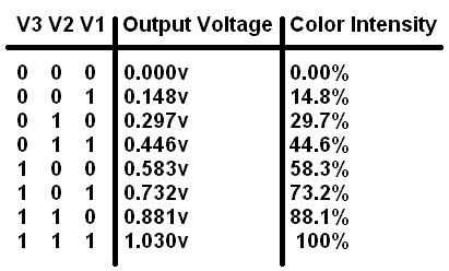
Simulating each of the possible On/Off states you can see how the output voltage varies from 1.0v down to 0.0v giving us 8 unique states. Now that we know the color intensity range and the resistor values that we need to use we can actually start building!
How does the VGA resistor DAC work? Well that's what the theory section is meant to answer! VGA color signals: Red, Green and Blue are all internally terminated through the monitor with a resistance of 75Ω which we can use to our advantage. If we add resistance to the output of any signal, a voltage divider will form decreasing the output voltage. Since VGA uses the analog voltage on the Red, Green and Blue color signals to denote color intensity, we now have a cheap and easy way to create lots of colors.
The VGA standard says that during active video display, the analog voltages on the R/G/B color signals correlates to their intensity. 1.0v is 100% color intensity and 0.0v is 0% intensity. This means if, for example, we want to be able to display 8 unique shades of Red, we will need to be able to create 8 unique voltages between 1.0v and 0.0v. So this means we need to choose some resistors to connect to the CPLD, so that we can create these analog voltages.

Using a simulation tool called Pspice we can create a netlist (picture above) that does all the ohm's law calculations for us. After playing around for a while with different resistor I settled on the ones seen above.
Simulating each of the possible On/Off states you can see how the output voltage varies from 1.0v down to 0.0v giving us 8 unique states. Now that we know the color intensity range and the resistor values that we need to use we can actually start building!