Hardware Design
With the schematic under our belts and the theory explained, it's time to get everything wired up. If you have built the CPLD development board already then the changes are minimal, if not, please see the tutorial and build it! I'm going to assume you have it ready to go and start wiring the VGA section.
Building The Circuit
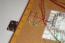
First get the new parts together and ready to start wiring, the picture below shows everything you need to get it wired up.

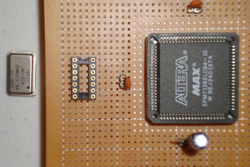
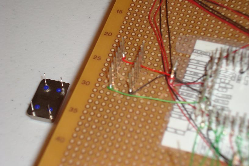
·First connect the 25.175 MHz oscillator. Take care: the dot on the can represents a no connect pin!

·Next get the 9 resistors and wire them to the CPLD I/O pins.
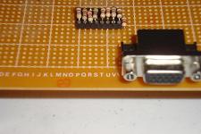
·Connect each group of 3 resistors to the Red, Green and Blue pins of the VGA Connector.

·Lastly, connect the Hsync, Vsync and Ground signals of the VGA connector.
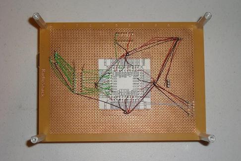
·The hardware addition is complete and now we just need to load the VHDL onto the CPLD.
With the schematic under our belts and the theory explained, it's time to get everything wired up. If you have built the CPLD development board already then the changes are minimal, if not, please see the tutorial and build it! I'm going to assume you have it ready to go and start wiring the VGA section.
Building The Circuit
First get the new parts together and ready to start wiring, the picture below shows everything you need to get it wired up.
·First connect the 25.175 MHz oscillator. Take care: the dot on the can represents a no connect pin!
·Next get the 9 resistors and wire them to the CPLD I/O pins.
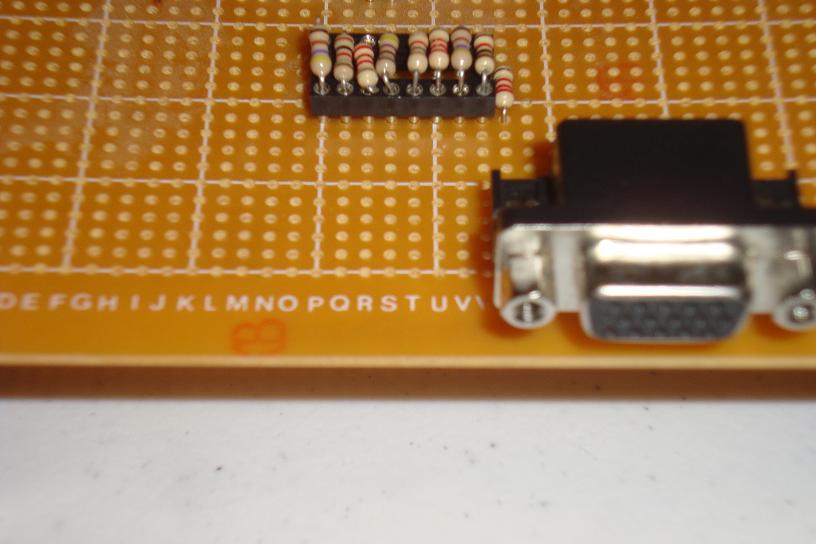
·Connect each group of 3 resistors to the Red, Green and Blue pins of the VGA Connector.
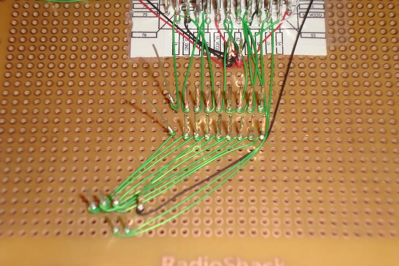
·Lastly, connect the Hsync, Vsync and Ground signals of the VGA connector.

·The hardware addition is complete and now we just need to load the VHDL onto the CPLD.