Making A Part In Eagle
This is my abridged version of making your own part in Eagle. Since I only care about connections and not so much functionality I won't worry about specifying particulars like which pins are power, ground or I/O's, it doesn't matter for a breakout board.
Creating a part in eagle is a 3 step process:
Building The Part Symbol
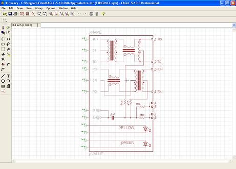
For the part symbol of my ethernet port, I borrowed the same symbol from a very similar part I found already in the Eagle library. Some types of parts don't exist in the Eagle library so unforuntately you might have to start from scratch for some parts.
Building The Part Footprint

The part leveraged from eagle's library had a vastly different footprint, so I had to go in and modify the drill holes, pads and pin locations for almost everything for my ethernet port. The easiest way to align things perfectly is to have your part's datasheet in front of you so that you can reference the exact dimensions of your part while building the foot print.
Connecting The Pins Together
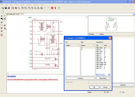
The last step in creating your own part in Eagle requires connecting the pins togther. This step maps the pins you defined in the Symbol to the pins defined in the layout so that when you build a design, the tool knows which wire is going where.
This is my abridged version of making your own part in Eagle. Since I only care about connections and not so much functionality I won't worry about specifying particulars like which pins are power, ground or I/O's, it doesn't matter for a breakout board.
Creating a part in eagle is a 3 step process:
- First - Build the part Symbol
- Second - Build the layout footprint
- Third - Connect the pins together
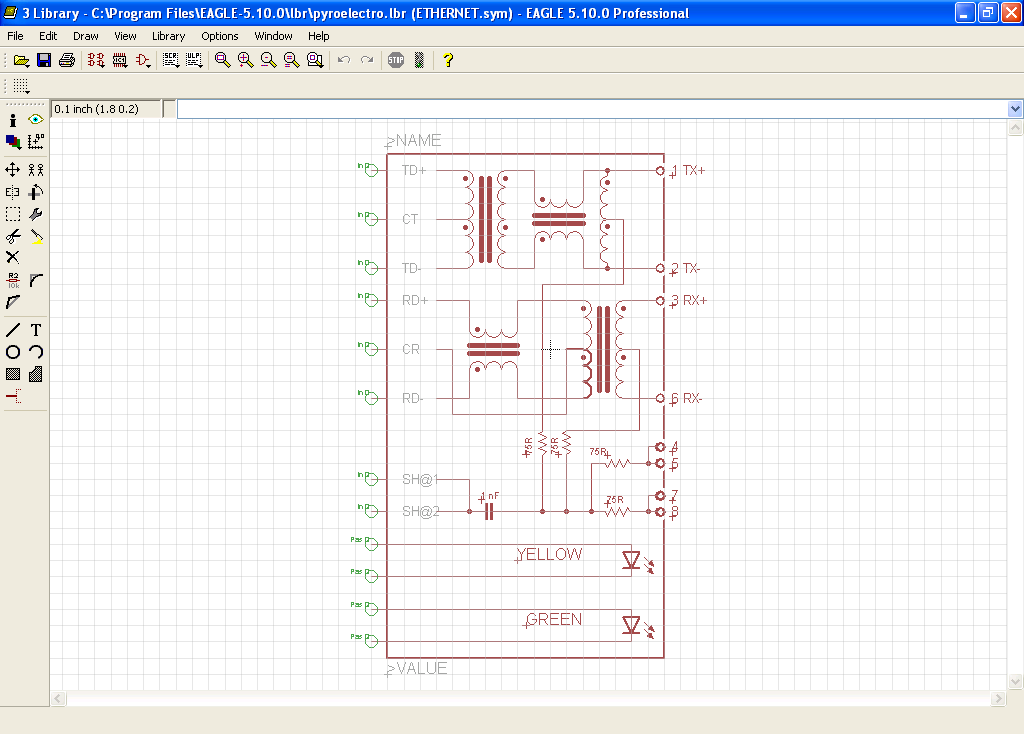
For the part symbol of my ethernet port, I borrowed the same symbol from a very similar part I found already in the Eagle library. Some types of parts don't exist in the Eagle library so unforuntately you might have to start from scratch for some parts.
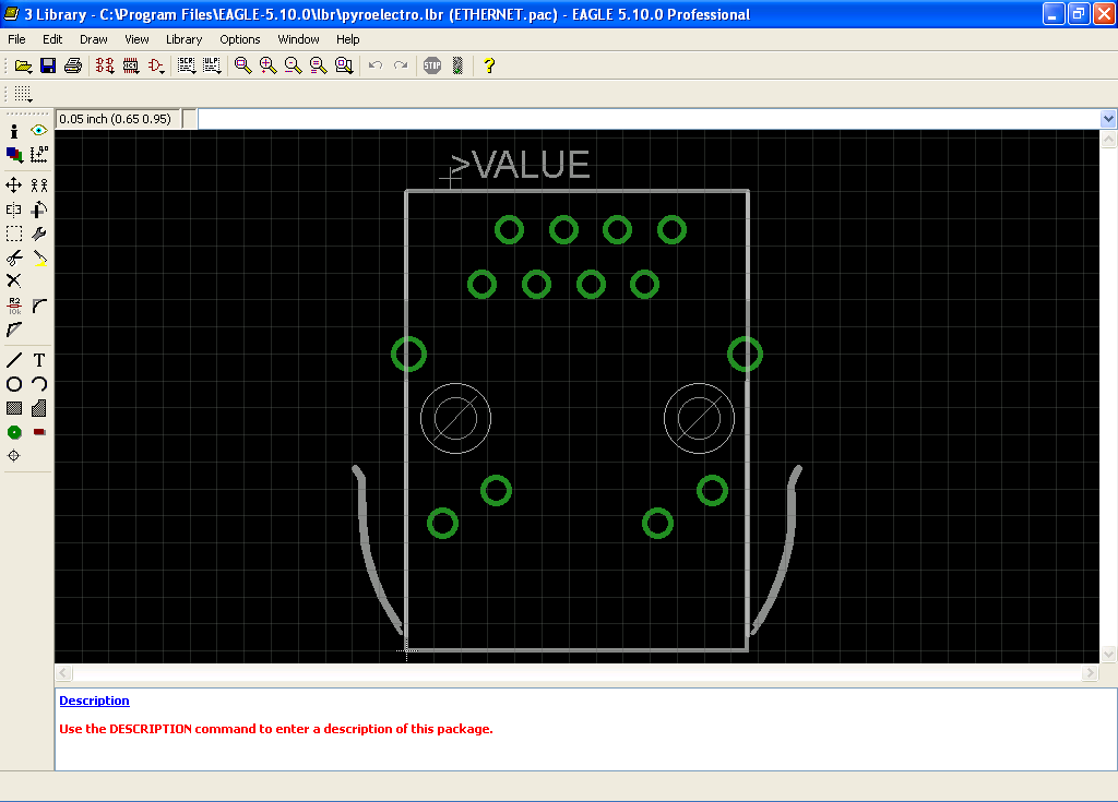
The part leveraged from eagle's library had a vastly different footprint, so I had to go in and modify the drill holes, pads and pin locations for almost everything for my ethernet port. The easiest way to align things perfectly is to have your part's datasheet in front of you so that you can reference the exact dimensions of your part while building the foot print.

The last step in creating your own part in Eagle requires connecting the pins togther. This step maps the pins you defined in the Symbol to the pins defined in the layout so that when you build a design, the tool knows which wire is going where.