Project Info
Author: Chris
Difficulty: Medium
Time Invested: 2 Hours
Prerequisites:
Take a look at the above
articles before continuing
to read this article.
Author: Chris
Difficulty: Medium
Time Invested: 2 Hours
Prerequisites:
Take a look at the above
articles before continuing
to read this article.
This article will show you how an accelerometer works, how it can be used to detect tilt and also how we can display that tilt 'value' visually on a large array of LEDs on my DE0-Nano breakout board. This way whenever we need to see if something is level, we can use this simple but fun tool to know, although don't count on multiple decimal precision here!
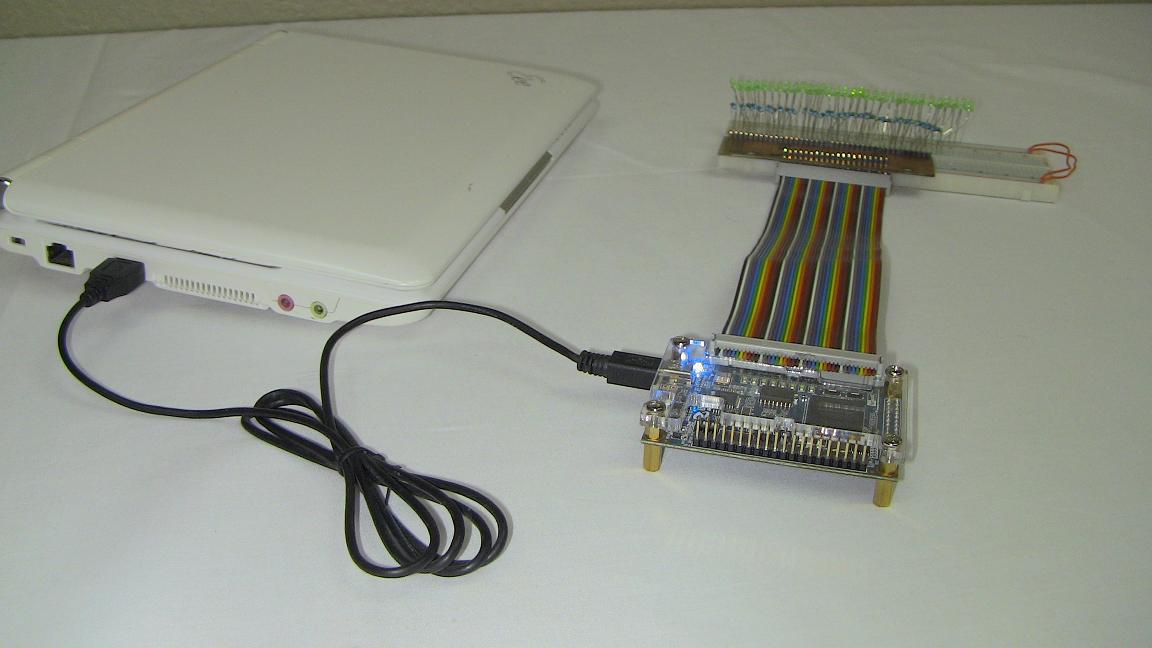
Purpose & Overview of this project
The goal of this project is to create a system that can interface with an accelerometer using digital communication, find out the currently detected g-force detection and then translate that information into a +/- 1g value that will tell us how much the DE0-Nano has been tilted. Output should appear on an array of 32 LEDs.
Since I want to use the breakout board I made in this project, you definitely need to have a DE0-Nano to follow along. The DE0-Nano has a Cyclone IV FPGA and the on-board accelerometer is an ADXL345 13 bit 3 axis accelermoeter, but we'll only use 1 axis of data.