An Overview Of The DE0-Nano FPGA Tilt Sensing
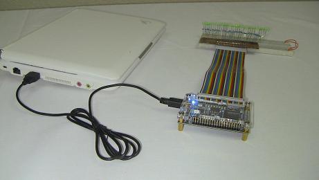
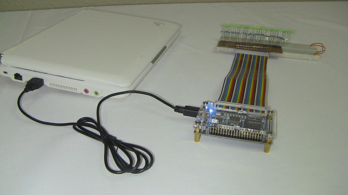
This whole project was meant to give you a way to have access to more of the DE0-Nano's functionality. They have two identical expansion headers but no easy way to access the 34 I/O pins on each one! Making a PCB at home should not seem like an impossible task and I hope that this article proves that to you. Yes my PCB didn't look very pretty, but it worked and took little money and only a few hours to build!
What To Do Now
There's many avenues you can explore now that you have an extra 34 Output and 4 input pins at your disposal and with easy access on a breadboard! Go start prototyping or take a look at any of my cpld or fpga tutorials and projects and build one of those. I would suggest making the DE0-Nano a brain for a robot, given its size, it could make an awesome tiny controller. Get to it!
Conclusion
Building PCBs at home can really be fun after you find out that it just takes a few times to get good at it, plus you save money and time. Breakout boards whether for the DE0-Nano, ethernet or VGA connectors are extremely useful for prototyping. This article took you through the process of building a specialized breakout board for the DE0-Nano with the state goal of putting 34 more digital outputs at our disposal. At that purpose, this project has been successful.
If you have any further questions, I implore you...don't be shy, take a look at the forums or ask a question there. I check them out regularly and love getting comments & questions.