Schematic Overview
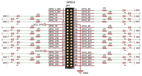
The schematic shown below skips over the expansion board connections and just assumed it works perfectly. Each I/O pin has a connection to a resistor and LED, but the input pins, grounds and VCC pins do not.
View Full Schematic
Schematic Specifics
Resistors and LEDs
Exactly 32 LEDs and 32 100Ω resistors are used and connected to the GPIO0 to GPIO32 outputs connected to the Cyclone IV FPGA on the DE0-Nano.
GPIO-0
There's actually two GPIO 40 pin expansion headers on the DE0-Nano. The one we'll be using is labeled as GPIO-0, so make note of that when you're designing in Altera's Quartus.
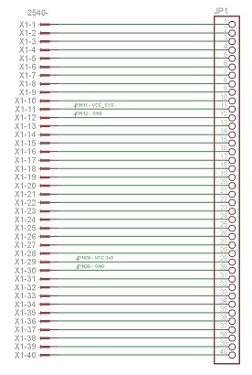
DE0 Nano Expansion Port
Below is the actual schematic used for the Pyro DE0-Nano breakout board. As you can see its just a bunch of straight-through pin to pin connections. That is why I omitted it from the schematic above for this project, it's really not necessary.
View Full Schematic
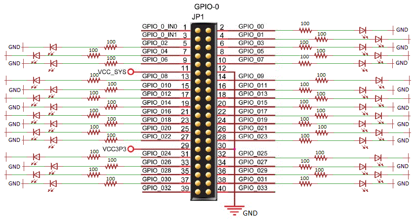
The schematic shown below skips over the expansion board connections and just assumed it works perfectly. Each I/O pin has a connection to a resistor and LED, but the input pins, grounds and VCC pins do not.
View Full Schematic
Schematic Specifics
Resistors and LEDs
Exactly 32 LEDs and 32 100Ω resistors are used and connected to the GPIO0 to GPIO32 outputs connected to the Cyclone IV FPGA on the DE0-Nano.
GPIO-0
There's actually two GPIO 40 pin expansion headers on the DE0-Nano. The one we'll be using is labeled as GPIO-0, so make note of that when you're designing in Altera's Quartus.
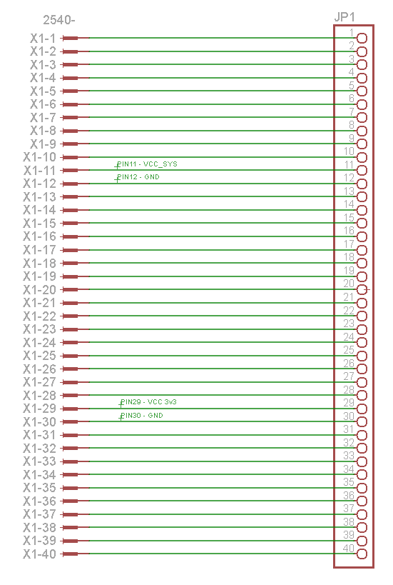
DE0 Nano Expansion Port
Below is the actual schematic used for the Pyro DE0-Nano breakout board. As you can see its just a bunch of straight-through pin to pin connections. That is why I omitted it from the schematic above for this project, it's really not necessary.
View Full Schematic