Project Info
Author: Chris
Difficulty: Medium
Time Invested: 2 Hours
Prerequisites:
Take a look at the above
articles before continuing
to read this article.
Author: Chris
Difficulty: Medium
Time Invested: 2 Hours
Prerequisites:
Take a look at the above
articles before continuing
to read this article.
In the past I have built many, many VGA based projects, but never with Arduino and so, in this article, we will use the Arduino UNO platform to simulate VGA signals using straight C code. This doesn't even come close to how video card designers do it, but it's a fun exercise in seeing how well we understand the timing of the Arduino and AVR microcontroller as well as the VGA protocol.
Purpose & Overview Of This Project
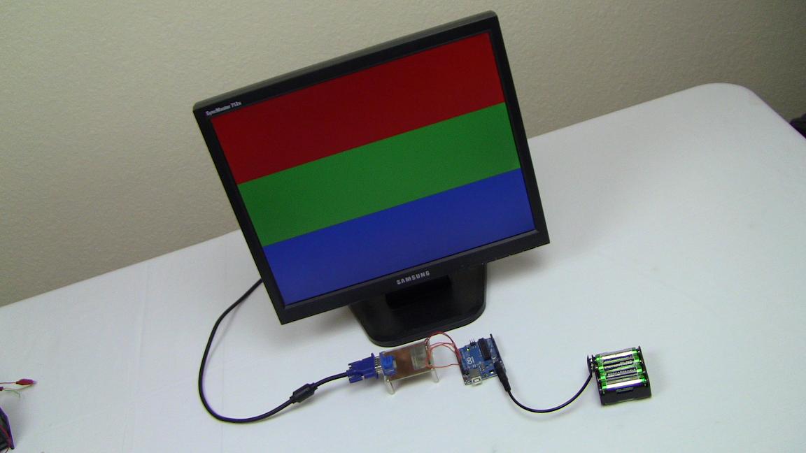
The purpose of this project is to use an Arduino UNO to output a standard Red, Green and Blue color pattern on a VGA computer monitor. In addition to an Arduino UNO I will use the small VGA connector breakout board I made in the Masochist's Video Card project to make it easier to connect to the monitor.
In order to output the Red, Green and Blue pattern to the VGA computer monitor, we have to agree on what timing resolution we'll be attempting to simulate. Since 800x600 uses nice round numbers, becaues of it's 40 MHz pixel clock, we'll shoot to simulate 800x600 resolution VGA and to output 200 lines of Red, 200 lines of Green and 200 lines of Blue. Since the Arduino UNO uses a 16 MHz clock, there is no way to have access to each pixel, thus we'll just focus on full-line lengths of color.