Schematic Overview
The schematic for this project is fairly large and you can see the complete schematic below. To explain what is happening here I will split it into two sections which I will call the analog and digital sections.
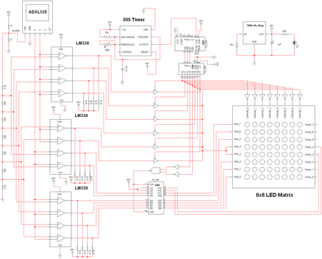
View Full Schematic
Analog Schematic Overview
The schemtic below (click to enlarge it) is the analog to digital conversion circuit. It has 12 comparators, 6 for the X axis and 6 for the Y axis. These comparators will output a logic '1' when in an active state (previously described in the theory section) otherwise they output a logic '0'. This output is then passed onto the digital circuit where it is parsed.
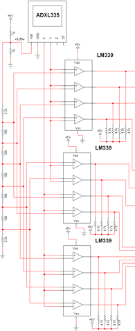
View Full Schematic
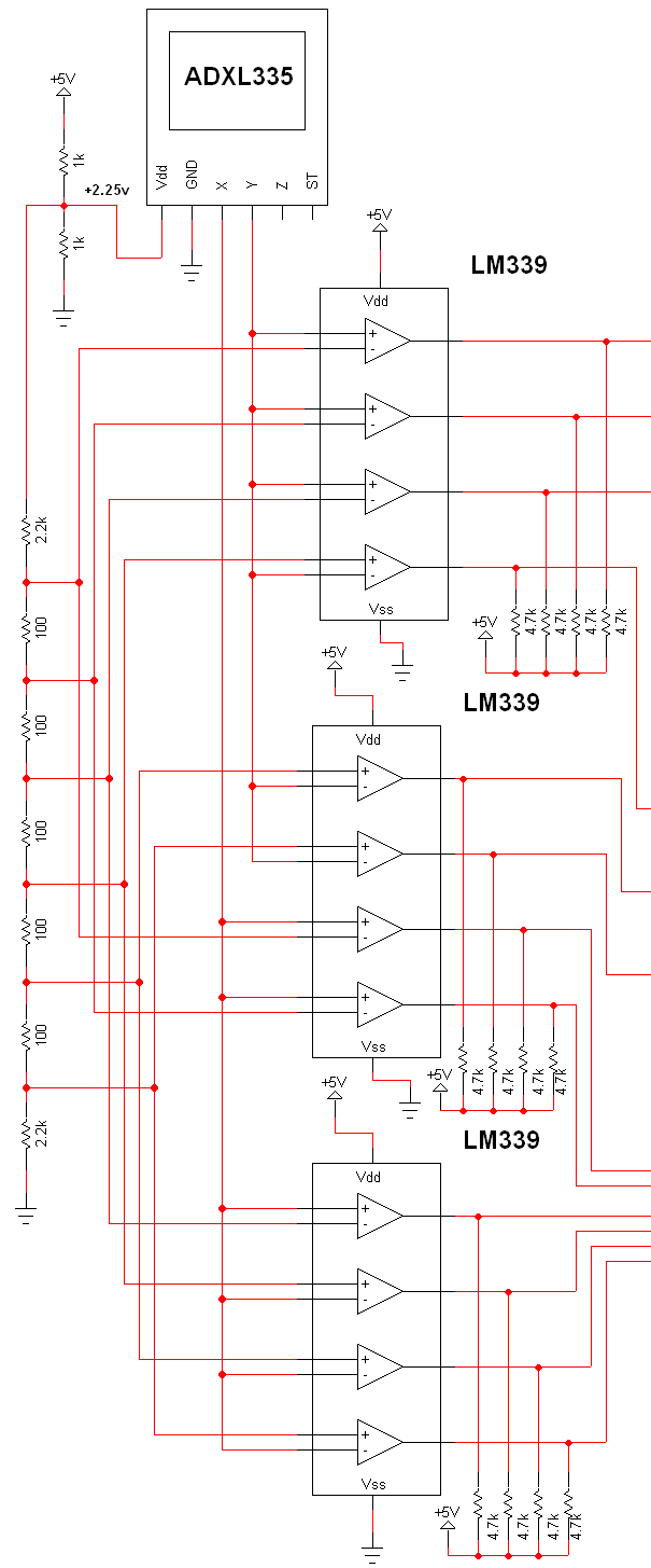
Schematic Specifics
LM339 Quad Comparator
The comparator used for this part of the circuit is the tried and true LM339. It has 4 comparators inside of it and runs off of a single power supply. Since we need 12 comparators in total, 3 LM339 IC's will be used.
Resistor Voltage Divider
Two voltage dividers are used. The first voltage divider is made up of two 1kΩ resistors which divides the intial +5v down and is then fed to the reference resistor voltage divider. The divided input voltage turns out to be +2.25v and it is also used to power the accelerometer. This part of the design could be simplified but I got a little lazy, sorry!
The schematic for this project is fairly large and you can see the complete schematic below. To explain what is happening here I will split it into two sections which I will call the analog and digital sections.

View Full Schematic
Analog Schematic Overview
The schemtic below (click to enlarge it) is the analog to digital conversion circuit. It has 12 comparators, 6 for the X axis and 6 for the Y axis. These comparators will output a logic '1' when in an active state (previously described in the theory section) otherwise they output a logic '0'. This output is then passed onto the digital circuit where it is parsed.
View Full Schematic
Schematic Specifics
LM339 Quad Comparator
The comparator used for this part of the circuit is the tried and true LM339. It has 4 comparators inside of it and runs off of a single power supply. Since we need 12 comparators in total, 3 LM339 IC's will be used.
Resistor Voltage Divider
Two voltage dividers are used. The first voltage divider is made up of two 1kΩ resistors which divides the intial +5v down and is then fed to the reference resistor voltage divider. The divided input voltage turns out to be +2.25v and it is also used to power the accelerometer. This part of the design could be simplified but I got a little lazy, sorry!