State Machine Theory
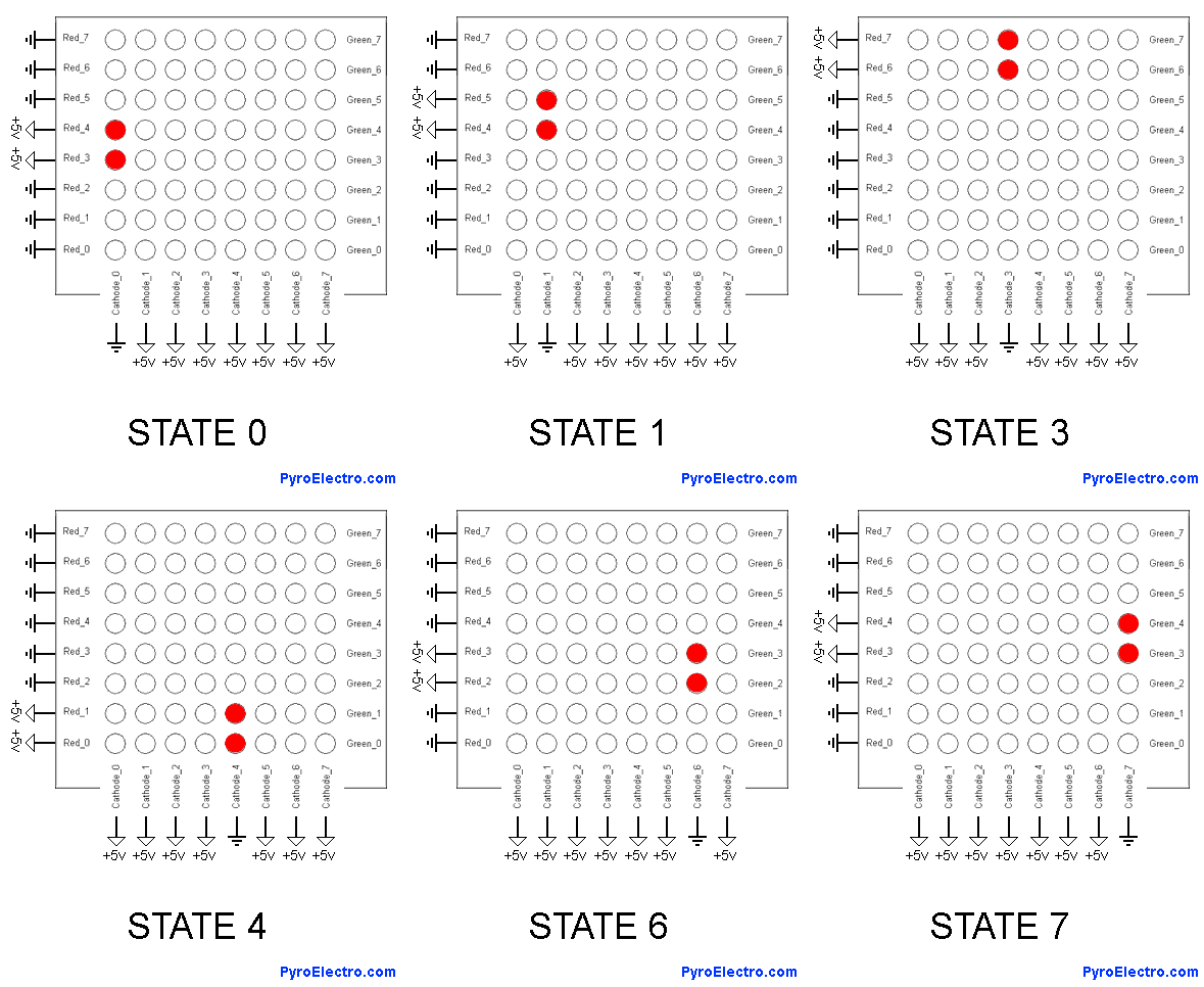
Now, let's take a look at the 8 state machine that we will use to drive the 8x8 matrix display. If you'll remember from before, the LED matrix can only access 1 column of LEDs at a time because each column shares a common cathode so we will need to cycle through each of the 8 columns and light up the appropriate LEDs. If you do this quickly enough, persistence of vision takes hold and it looks as if the LEDs are always on.
State Machine Outputs

The short animation above shows you the 8 states necessary to access all of the LEDs. In our design we will use a de-multiplexer (74-238) through some hex inverters to offer each of the 8 cathodes a ground path, one at a time. This way we can use that same select line from the 74-238 to enable LED output buffers to light up specific LEDs.
To know which LEDs should be lit up, the output from the analog to digital converter from the previous section will be input into these LED output buffers which will then light up LEDs depending upon the current magnitude of tilt. Enough theory! Let's see the schematic design!
Now, let's take a look at the 8 state machine that we will use to drive the 8x8 matrix display. If you'll remember from before, the LED matrix can only access 1 column of LEDs at a time because each column shares a common cathode so we will need to cycle through each of the 8 columns and light up the appropriate LEDs. If you do this quickly enough, persistence of vision takes hold and it looks as if the LEDs are always on.

The short animation above shows you the 8 states necessary to access all of the LEDs. In our design we will use a de-multiplexer (74-238) through some hex inverters to offer each of the 8 cathodes a ground path, one at a time. This way we can use that same select line from the 74-238 to enable LED output buffers to light up specific LEDs.
To know which LEDs should be lit up, the output from the analog to digital converter from the previous section will be input into these LED output buffers which will then light up LEDs depending upon the current magnitude of tilt. Enough theory! Let's see the schematic design!