Digital Schematic Overview
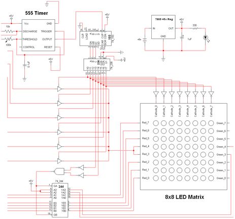
The digital side of this project is considerably more involved with several things happening at the same time and controlling output. The schematic for the digital side of the circuit can be seen below.
View Full Schematic
Schematic Specifics
State Machine
The first thing to see is the 3 devices that form the state machine: the 555 timer, 74-193 counter and 74-238 de-multiplexer. The 8 state output signals from the 74-238 are enable signals that are fed into the 8x8 matrix and into each LED driver buffer. The 555 timer uses a variable resistor, only so I could demonstrate in the video how the persistence of vision illusion makes the LED matrix appear always on.
Buffers
There are two types of buffers used. The first type are the individual buffers found in the 74-126. These individual buffers are all connected to the #3 and #4 red LEDs as they control the horizontal part of the LED output.
The second type is the 74-244 octal buffer, the other 6 input signals from the analog circuit are input to this buffer. The output is connected to all other red pins, except #3 and #4, as they will form the 'vertical' part of the LED output. Also, I wanted the center four LEDs to shine green, so I used the extra 2 buffers on the 74-244 and connected them to green #3 and #4.
7805 Power Regulator
Back to something easier. The power regulator for this circuit is a standard 7805 +5v regulator with a filtering cap on the +5v output, a current limiting resisitor and power LED. No surprises here.
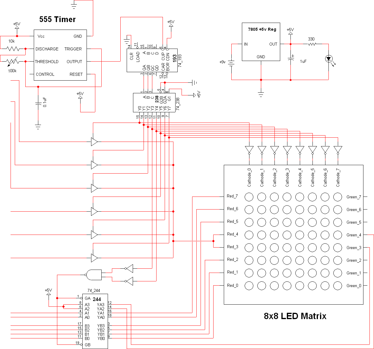