Custom ADC Theory
Since the accelerometer's output is an analog voltage, we will need to convert that into a useable digital form for display on the LED matrix. To do that we will make our own analog to digital converter (ADC) using comparators. To build this converter we will use three things, a voltage divider with resistors, a comparator, and the analog voltage from the accelerometer. First let's take a quick look at the output from the accelerometer.
ADXL 335 Accelerometer Theory
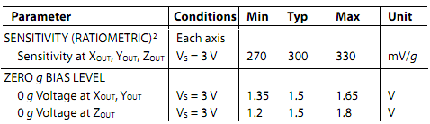
The basic way that the ADXL 335 accelerometer works is that all output is proportional to your supply input voltage. Looking only at the X and Y axis information above, if your supply voltage is +3v, then when X and Y axis are at 0g they will output +1.5v. ±1 g-force applied to the X or Y axis would result in the +1.5v changing by ± 300mv. With this information in mind, let's continue and look at how the custom ADC will be built.
Reference Voltage Divider
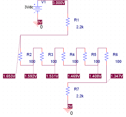
The first thing we will need for the analog to digital converter is some reference voltages. The idea here is to have a constant voltage that never changes, this way if we compare it to the X or Y axis output from the accelerometer, we can find out if the constant is larger or smaller, giving us magnitude. Notice above how with +3v input, there are 3 states above the 0g center of +1.5v and 3 states below. These will signify what order magnitude above or below 0g, the X or Y axis is at.
Analog To Digital Converter Via Comparator
 Positive
G-Force Comparison Negative G-Force Comparison
Positive
G-Force Comparison Negative G-Force Comparison
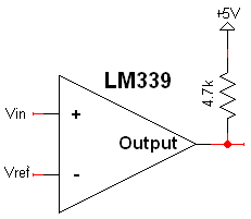
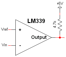
The final step in our analog to digital converter is inputing the reference voltage and the accelerometer x or y axis voltage into the comparator. Two configurations will be used for each accelerometer axis. The first configuration will send a logic '1' out the output, when the reference voltage is higher than the input voltage. This will be good for comparing the increasing accelerometer output data with reference voltages. The second configuration will send a logic '1' when the input voltage is lower than the reference voltage. This will be useful for when the accelerometer output voltage is decreasing, during negative g-force detection.
There's 6 reference voltages, 3 for positive g-forces, 3 for negative g-forces and we have 2 axis total (X and Y). So, in the end we will need to use 12 comparators.
Since the accelerometer's output is an analog voltage, we will need to convert that into a useable digital form for display on the LED matrix. To do that we will make our own analog to digital converter (ADC) using comparators. To build this converter we will use three things, a voltage divider with resistors, a comparator, and the analog voltage from the accelerometer. First let's take a quick look at the output from the accelerometer.
The basic way that the ADXL 335 accelerometer works is that all output is proportional to your supply input voltage. Looking only at the X and Y axis information above, if your supply voltage is +3v, then when X and Y axis are at 0g they will output +1.5v. ±1 g-force applied to the X or Y axis would result in the +1.5v changing by ± 300mv. With this information in mind, let's continue and look at how the custom ADC will be built.
The first thing we will need for the analog to digital converter is some reference voltages. The idea here is to have a constant voltage that never changes, this way if we compare it to the X or Y axis output from the accelerometer, we can find out if the constant is larger or smaller, giving us magnitude. Notice above how with +3v input, there are 3 states above the 0g center of +1.5v and 3 states below. These will signify what order magnitude above or below 0g, the X or Y axis is at.
Positive
G-Force Comparison Negative G-Force Comparison
The final step in our analog to digital converter is inputing the reference voltage and the accelerometer x or y axis voltage into the comparator. Two configurations will be used for each accelerometer axis. The first configuration will send a logic '1' out the output, when the reference voltage is higher than the input voltage. This will be good for comparing the increasing accelerometer output data with reference voltages. The second configuration will send a logic '1' when the input voltage is lower than the reference voltage. This will be useful for when the accelerometer output voltage is decreasing, during negative g-force detection.
There's 6 reference voltages, 3 for positive g-forces, 3 for negative g-forces and we have 2 axis total (X and Y). So, in the end we will need to use 12 comparators.