Amplifer Output (Second Stage)
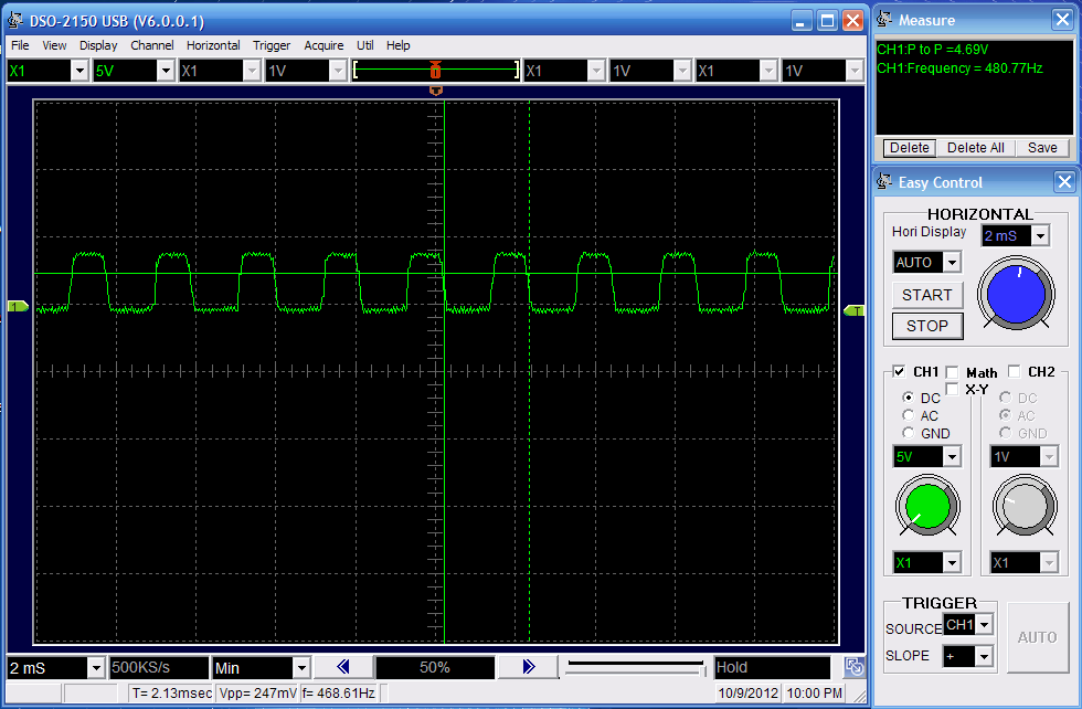
Now, we'll take a look at the output from the 2nd amplifier stage. This second stage should be more than enough to get our original 22mv received signal back up to the square wave form we originally transmitted.
In The Schematic:
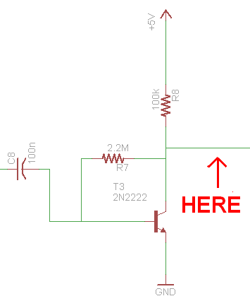
Measured @ 'Here':
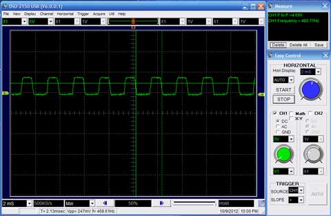
As you can see above, the square wave looks very much like what we transmitted from the transmitter. The peak voltages are at +4.69v and +0v, so the signal is ready to be sent to the 555 timer's inputs.
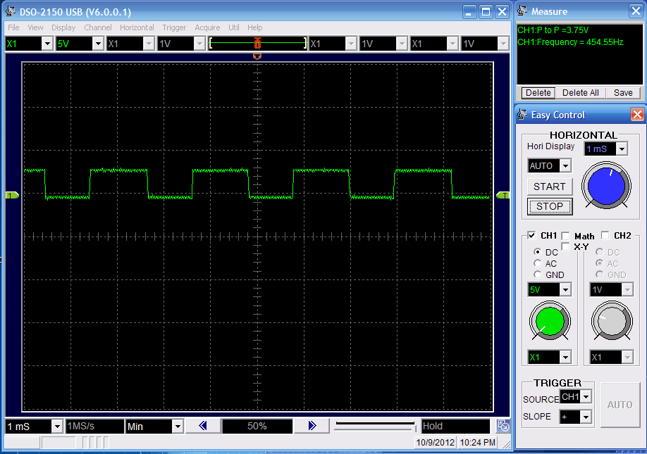
555 Timer Output
We're actually using the 555 timer as a comparator. Whenever the input voltage hits above +(2/3)Vcc or below +(1/3)Vcc the 555 timer changes state. It also acts as a primitive filter against noise spikes, but not very effectively.
In The Schematic:
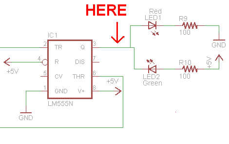
Measured @ 'Here':
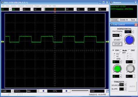
As you can see, the output from the 555 timer is just like the square-wave we generated with the 555 timer on the transmitter. One curious thing does remain about this end result...the frequency seems to have jumped up by 100 Hz. Unfortunately, I have no great explanation for why that occured.
Now, we'll take a look at the output from the 2nd amplifier stage. This second stage should be more than enough to get our original 22mv received signal back up to the square wave form we originally transmitted.
As you can see above, the square wave looks very much like what we transmitted from the transmitter. The peak voltages are at +4.69v and +0v, so the signal is ready to be sent to the 555 timer's inputs.
555 Timer Output
We're actually using the 555 timer as a comparator. Whenever the input voltage hits above +(2/3)Vcc or below +(1/3)Vcc the 555 timer changes state. It also acts as a primitive filter against noise spikes, but not very effectively.
As you can see, the output from the 555 timer is just like the square-wave we generated with the 555 timer on the transmitter. One curious thing does remain about this end result...the frequency seems to have jumped up by 100 Hz. Unfortunately, I have no great explanation for why that occured.