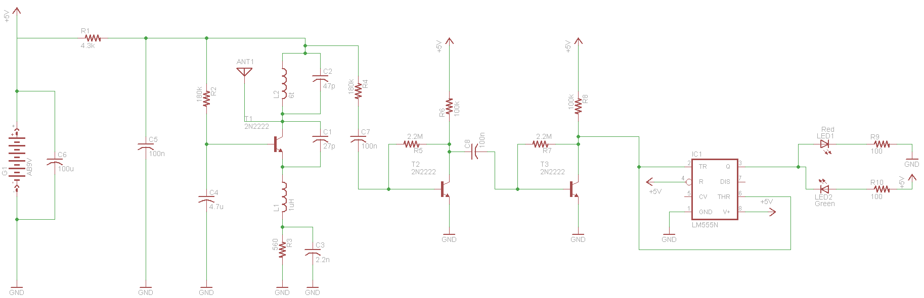
The schematic for this project flows naturally from left to right. Beginning at the antenna and the regenerative receiver front-end, then flowing through the amplification stages and then into the 555 timer.
View Full Schematic
Schematic Specifics
Front-End Regenative Receiver
This is a very common regenerative receiver front-end that you can find in circuits all over the web. I tailored the parts used to what I had laying around, generally you can tweak part values a little bit, with the exception of L2 and C2 which are your tuning circuit (tank circuit) for 27.145 MHz.
Amplifier Stages
Two amplifier stages exist in the middle of the schematic. They are used to 'rail' the signal back to its square-wave digital form of either +5v or +0v. I'm pretty sure that these amplifiers could be tweaked to get better performance, however the current design should work well enough for our requirements.
555 Timer Receiver Comparator
The amplified signal makes its way to the 555 timer in the form of its original square wave where this 555 timer uses the voltage detected with internal comparators to create an output that turns on the green LED.
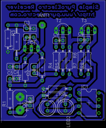
Board Layout Overview
The board layout for this project was done in a similar way as the schematic. The front-end receiver can be found on the top left side of the board, then the amplifier stages on the top right and finally the 555 timer and our output LEDs at the bottom right side.
Board Layout Specifics
Ground Plane
Just like with the transmitter, it's pretty important to have a ground plane for the receiver to act as a better antenna and keep extra noise out of the circuit. A solid ground plane would be very ideal, however for simplicity's sake we'll use a chopped up one with traces.
Trace Widths
I just chose a nice thick width that would transfer over nicely when building the PCB, however smaller trace widths seem to be a better choice when designing RF circuits...but at these low frequencies I don't believe there will be any performance benefit.
Shamless Logo Plug
My PC board had extra space so I plugged in PyroElectro.com. You'll notice the text is backwards, this is because during the toner transfer process, a bottom layer is technically printed out backwards, but once on the PCB it reads correctly.