Tuning Circuit (Tank Circuit) Output
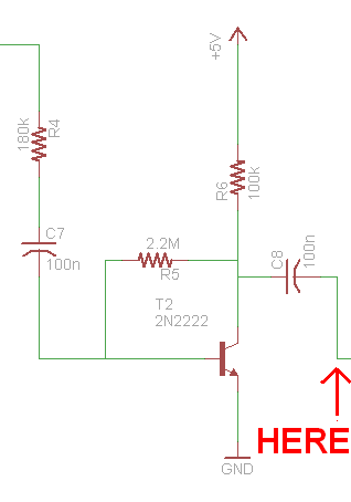
After the wizardry that is our standard renegerative front-end receiver circuit, we will be able to see some initial output receiver from our transmitter. The point in the schematic we'll look at first is right after the LC tuning circuit and DC blocking capacitor:
In The Schematic:
![]()
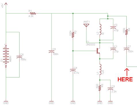
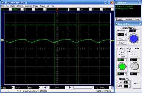
Measured @ 'Here':
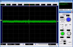
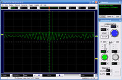
On the Left side there is a picture of that point when nothing is being transmitted. Compare that to the Right side which shows what that point in the schematic looks like when the transmitter is actively transmitting. You can see our carrier is making it through the LC circuit as it should be, vs. the background noise measurement, which is just noise.
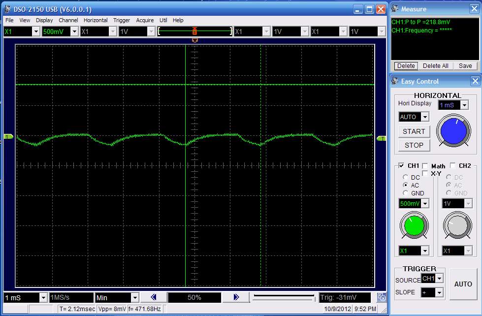
First Amplifier Output
Since our signal made it through the LC tuning circuit like we expected, we now need to amplify the heck out of it to get it back to a level where you can actually use it, below you can see the output from the first amplification stage:
In The Schematic:
Measured @ 'Here':
This output looks a lot larger than our 22mv input at about 218mv, but its not yet good enough to be used with our 555 timer turned comparator. So let's amplify the signal once more.
After the wizardry that is our standard renegerative front-end receiver circuit, we will be able to see some initial output receiver from our transmitter. The point in the schematic we'll look at first is right after the LC tuning circuit and DC blocking capacitor:


On the Left side there is a picture of that point when nothing is being transmitted. Compare that to the Right side which shows what that point in the schematic looks like when the transmitter is actively transmitting. You can see our carrier is making it through the LC circuit as it should be, vs. the background noise measurement, which is just noise.
First Amplifier Output
Since our signal made it through the LC tuning circuit like we expected, we now need to amplify the heck out of it to get it back to a level where you can actually use it, below you can see the output from the first amplification stage:
Measured @ 'Here':