Hardware Design
There are two parts to the hardware design of this project. Making the PCB from the schematic/board layout section and then assembling the PCB together by soldering all the parts into it. First, let's get started with the PCB fabrication.
Making The PCB
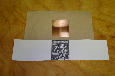
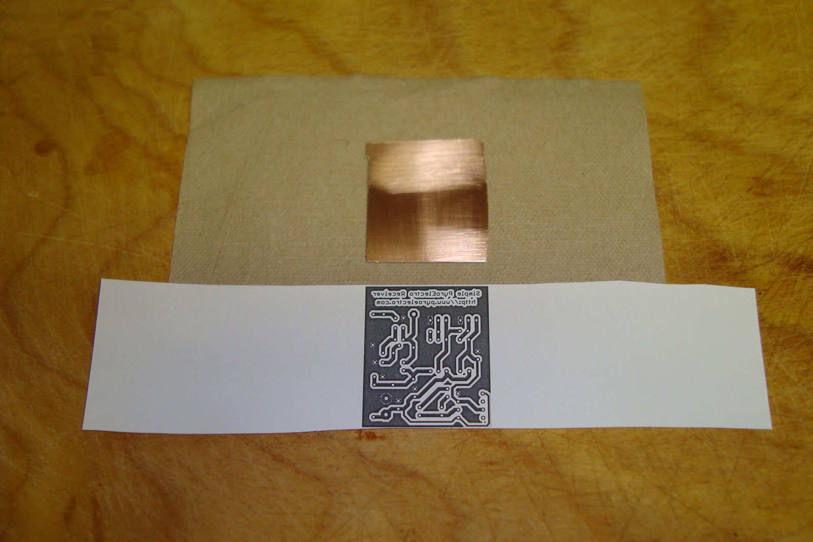
If you've never made your own PCB before, you'll want to go through my DIY PCB tutorial before continuing here. First I printed out the PCB Artwork Layout Design On Some Glossy Paper:
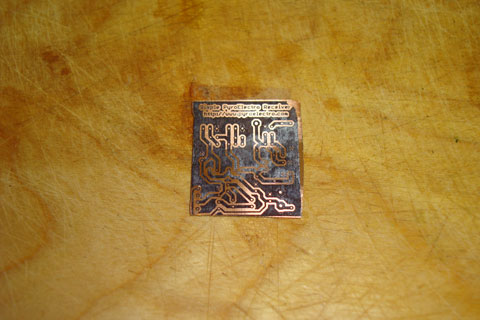
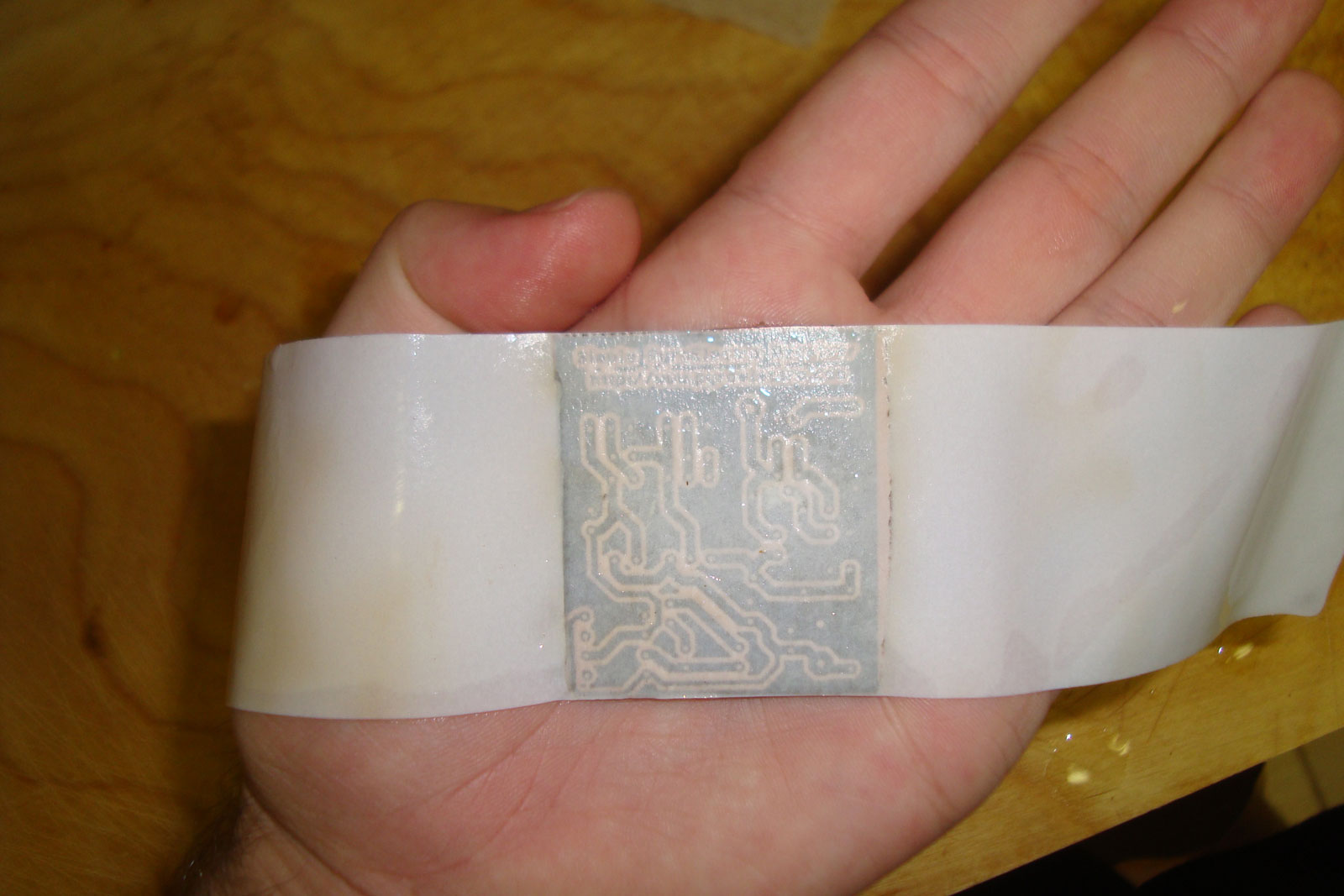
·Next I Ironed on the board artwork and then soaked it in water so the paper is easier to remove from the PC board.

·Below you can see the board with the toner transferred onto it (mostly) successfully. Some toner on the upper right side didn't transfer so well, but it won't make much of a difference.
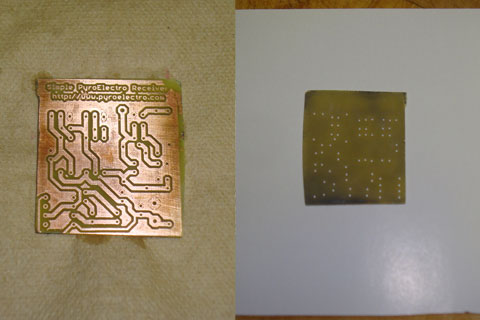
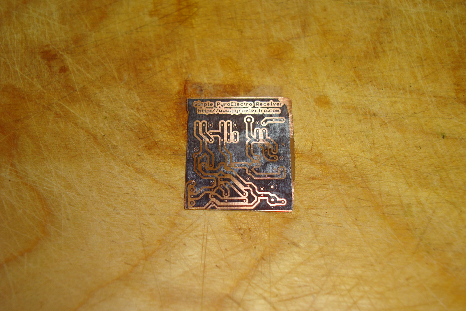
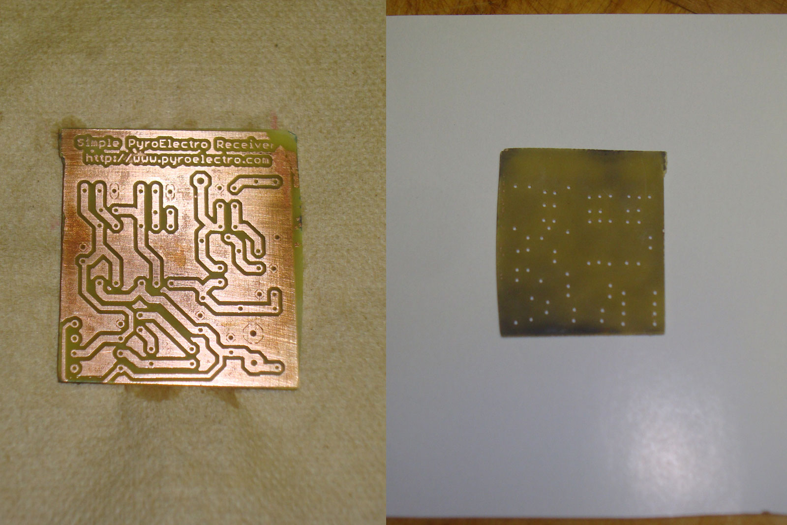
·Next, etch the copper away with some ferric chloride and then drill all the holes. Then the board looks like this:
·Now that our PCB is made, let's assemble all the parts onto it!
There are two parts to the hardware design of this project. Making the PCB from the schematic/board layout section and then assembling the PCB together by soldering all the parts into it. First, let's get started with the PCB fabrication.
Making The PCB
If you've never made your own PCB before, you'll want to go through my DIY PCB tutorial before continuing here. First I printed out the PCB Artwork Layout Design On Some Glossy Paper:
·Next I Ironed on the board artwork and then soaked it in water so the paper is easier to remove from the PC board.
·Below you can see the board with the toner transferred onto it (mostly) successfully. Some toner on the upper right side didn't transfer so well, but it won't make much of a difference.
·Next, etch the copper away with some ferric chloride and then drill all the holes. Then the board looks like this:
·Now that our PCB is made, let's assemble all the parts onto it!