Theory of Operation
This theory of operation section will focus on 3 main portions of the simple rf receiver. First we'll look at one of the more crucial components, the inductor used for tuning, then we'll continue on and look at the output from the receiver (while the transmitter is transmitting) at various points in the circuit all the way to the 555 timer's output.
The Inductor Coil
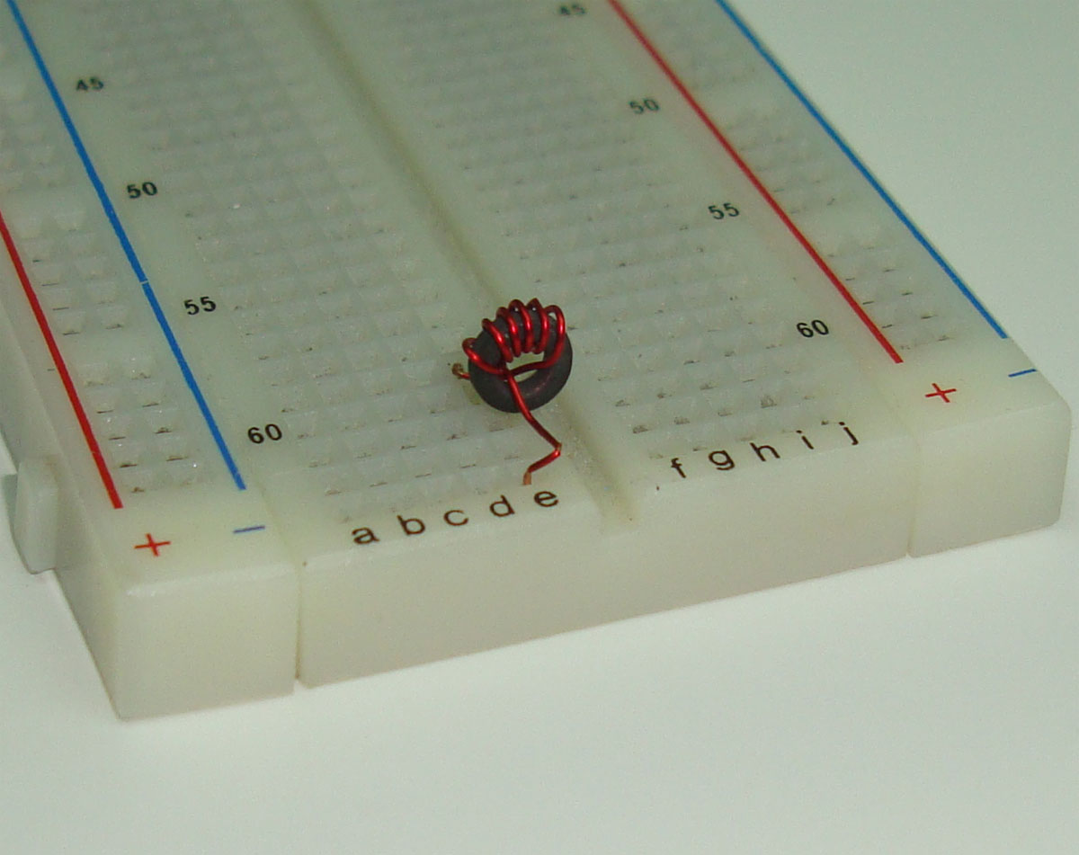
Building the 6 turn inductor coil correctly for this project extremely important. You need to have a ferrit core or toroid core of AL=25 to get the correct inductance. I chose to use a toroid because its easier to vary for when you need to get the proper tuned inductance. So building the coil is not as bad as it sounds, take some magnet wire and your ferrite core and wrap the magnet wire around the core 6 times like in the picture below:

Magnetic wire is coated in a tough insulator that you either burn off with a soldering iron, or scrap off with wire cutters. I opted to scrape off the insulator as you can see above. In the picture below you can see the magnet wire is wrapped around the toroid a little losely so that the wire can be pushed closer together or further apart to vary the inductance value of the toroid inductor.

You can look up the formula for a toroid core with AL=25 and 6 turns of AWG26 magnetic wire and calculate the inductance straight through math. When I measured the inductance of this homemade inductor it came out to about 0.7uH. But this can easily vary +/- 0.200uH by pushing the magnetic wire closer together or pulling it further apart.
This theory of operation section will focus on 3 main portions of the simple rf receiver. First we'll look at one of the more crucial components, the inductor used for tuning, then we'll continue on and look at the output from the receiver (while the transmitter is transmitting) at various points in the circuit all the way to the 555 timer's output.
The Inductor Coil
Building the 6 turn inductor coil correctly for this project extremely important. You need to have a ferrit core or toroid core of AL=25 to get the correct inductance. I chose to use a toroid because its easier to vary for when you need to get the proper tuned inductance. So building the coil is not as bad as it sounds, take some magnet wire and your ferrite core and wrap the magnet wire around the core 6 times like in the picture below:
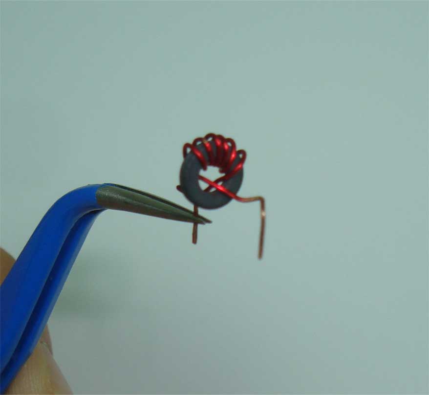
Magnetic wire is coated in a tough insulator that you either burn off with a soldering iron, or scrap off with wire cutters. I opted to scrape off the insulator as you can see above. In the picture below you can see the magnet wire is wrapped around the toroid a little losely so that the wire can be pushed closer together or further apart to vary the inductance value of the toroid inductor.