Project Info
Author: Chris
Difficulty: Advanced
Time Invested: 4 Hours
Prerequisites:
Take a look at the above
articles before continuing
to read this article.
Author: Chris
Difficulty: Advanced
Time Invested: 4 Hours
Prerequisites:
Take a look at the above
articles before continuing
to read this article.
In this article we will build a simple rf receiver module that works at 27 mhz and turns on an LED anytime the signal from the transmitter is detected. A very simple idea, but as you will soon find out, a lot goes into making it a reality. We'll be making our own PCB for this circuit, so get out the ferric chloride and copper clad PC board.
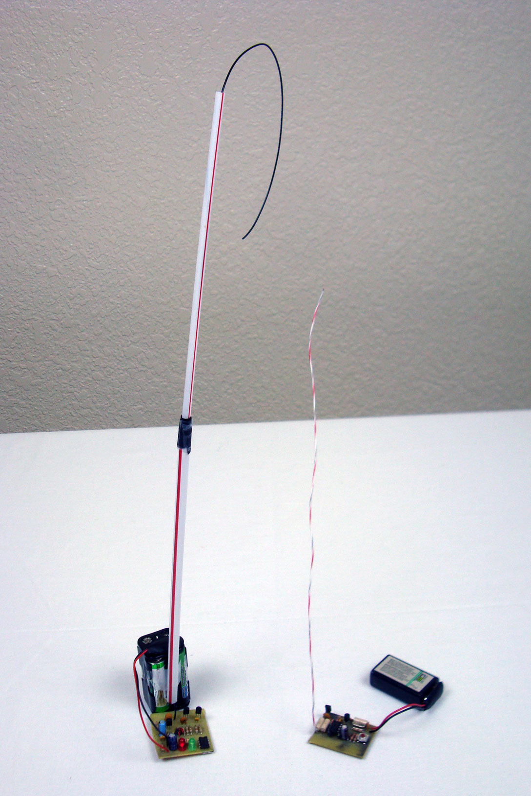
Purpose & Overview Of This Project
The goal of this project is to make an RF receiver front end to capture the 27 MHz signal that we're expecting, connect that to two amplifier stages and then to use the originally transmitted signal to turn an LED on. This processs is very much the opposite of how the transmitter worked.
The front end receiver will be a very old regenative design that has been used for decades. The amplifier stages will be single transistor amplifiers that basically rail the signal between power and ground. The final part is a 555 timer which will be used as a comparator which will tell us whether our signal has made it through or not by lighting up a green LED.