Eagle Schematic/Layout Files
Archived Layout PDF + Schematic/Layout For Eagle:
FM_Bug_Transmitter_layout.zip
Archived Layout PDF + Schematic/Layout For Eagle:
FM_Bug_Transmitter_layout.zip
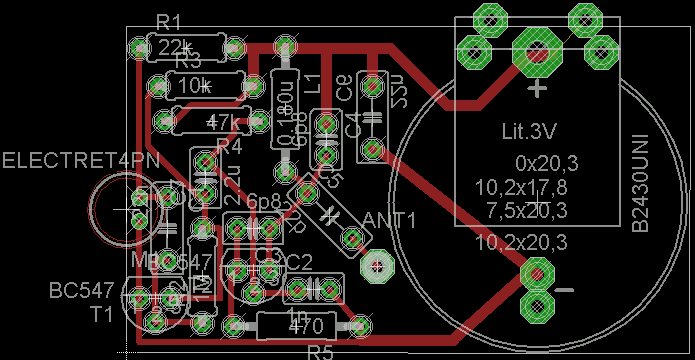
Using Eagle Layout Editor, I entered in the fm bug schematic and then I laid the parts out on the smallest sized board I could. The final size of the board end up being about 4.5 by 2.6cm ~~ 1.7" by 1" for you non metric folk.
Making The PC Board
·Print out the layout on glossy paper, have the 5cm x 3cm copper board ready.
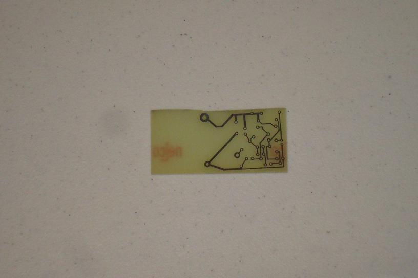
·Use a normal iron to apply heat to the glossy paper, transferring the toner.
·Toner transfer done. Use a felt pen to touch up any missing traces.
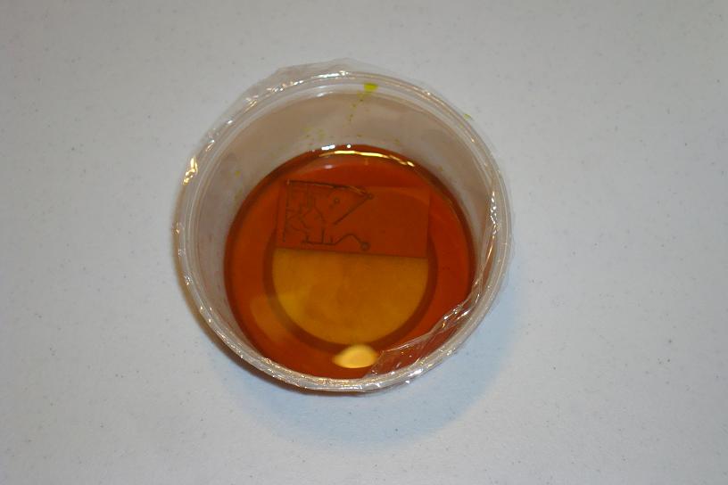
·Etch the board using ferric chloride to eat the copper.
·Etching is done, use a sponge to wipe off the toner.
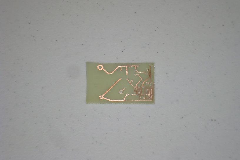
·Drill the holes for the parts and you're ready to assemble it together!