The LC Oscillator Is A Tank Circuit
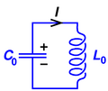
It was discovered pretty early on in electronics that if you put an inductor and capacitor in parallel with each other, they will resonate at a specific frequency. Ideally charge flows back and forth between the 'top' and 'bottom' capacitor plates generating this resonant frequency (similar to how a pendulum swings back and forth). Because charge seems to get trapped in ths circuit it got the bizarre name of 'The Tank Circuit' which is very common throughout all electronics.
The LC Oscillator Formula
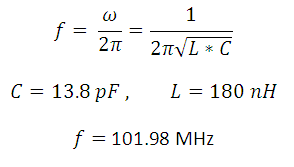
If we plug in the values seen above, the oscillator should create the correlating frequency and in an ideal world that is what happens. The big problem for us is we don't live in an ideal world and things like extra resistance and stray capacitance can effect the quality and frequency of the oscillator.
This means we need to keep parts close together to avoid large resistances and add a capacitor for feedback across the Common and Emitter pins of the transistor to keep the oscillator going. This type of oscillator is extremely sensitive and changes in other parts of a circuit can have an effect on the actual resonant frequency.
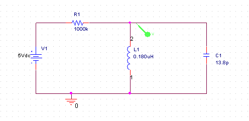
An LC Oscillator Simulation
Spice is usually the tool of choice when simulating any electronic circuits. For this example I drew up a quick and dirty LC oscillator. The schematic can be seen below. This circuit would not be good for practical use because there is very little current flowing into the oscillator, but it does a good job of illustrating how the oscillator works.
The green probe looks at the voltage at that specific point over a period of time. In this case, since the expected frequency is 101.9 MHz, the period of the frequency will be around 10nS. The time range we'll look at is set to 60nS and the results can be seen below.
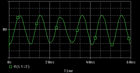
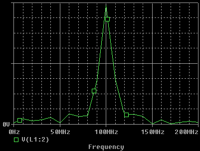
If you look closely you can see the period is just about 10nS as expected. But to triple check, I did an FFT on the signal which gave me the frequeny domain graph, which more obviously points out that the peak frequency generated by the circuit is around 101.9 MHz.
Now that we have a little more understanding of how the oscillator is made, how the audio signal is amplified and how the FM signal is created let's move forward and actually build this thing!
It was discovered pretty early on in electronics that if you put an inductor and capacitor in parallel with each other, they will resonate at a specific frequency. Ideally charge flows back and forth between the 'top' and 'bottom' capacitor plates generating this resonant frequency (similar to how a pendulum swings back and forth). Because charge seems to get trapped in ths circuit it got the bizarre name of 'The Tank Circuit' which is very common throughout all electronics.
The LC Oscillator Formula
If we plug in the values seen above, the oscillator should create the correlating frequency and in an ideal world that is what happens. The big problem for us is we don't live in an ideal world and things like extra resistance and stray capacitance can effect the quality and frequency of the oscillator.
This means we need to keep parts close together to avoid large resistances and add a capacitor for feedback across the Common and Emitter pins of the transistor to keep the oscillator going. This type of oscillator is extremely sensitive and changes in other parts of a circuit can have an effect on the actual resonant frequency.
An LC Oscillator Simulation
Spice is usually the tool of choice when simulating any electronic circuits. For this example I drew up a quick and dirty LC oscillator. The schematic can be seen below. This circuit would not be good for practical use because there is very little current flowing into the oscillator, but it does a good job of illustrating how the oscillator works.
The green probe looks at the voltage at that specific point over a period of time. In this case, since the expected frequency is 101.9 MHz, the period of the frequency will be around 10nS. The time range we'll look at is set to 60nS and the results can be seen below.
If you look closely you can see the period is just about 10nS as expected. But to triple check, I did an FFT on the signal which gave me the frequeny domain graph, which more obviously points out that the peak frequency generated by the circuit is around 101.9 MHz.
Now that we have a little more understanding of how the oscillator is made, how the audio signal is amplified and how the FM signal is created let's move forward and actually build this thing!