Schematic Overview
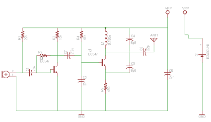
Here is the circuit for the FM Bug. In total there are 18 core components that are needed for the fm transmitter to work properly. The far left side has the electret microphone and then things move electrically to the right until they hit the antenna.
View Full Schematic
Schematic Specifics
Electret Microphone
Don't let this microphone fool you, it's extremely sensitive albeit a bit clunky and big. You could shop around for a smaller microphone I'm sure but for this project, a standard electret microphone does the trick. The input is pulled high with a 22k resistor and passed to the amplifier circuit.
Amplifier Circuit
The amplifier's job in this circuit is to take the audio input and beef up the voltage/current so that when it gets transmitted it travels further. More amplification means more higher fm transmitting power and longer range.
Oscillator/Mixer Circuit
The last portion of the circuit with the 2nd BC547 is where the oscillator for the FM frequency is generated and mixed with the audio signal inorder to form the frequency modulation used for FM radio. Don't worry, if all this is described a bit too quickly, the theory will be desribed more indepth in the next section.
Here is the circuit for the FM Bug. In total there are 18 core components that are needed for the fm transmitter to work properly. The far left side has the electret microphone and then things move electrically to the right until they hit the antenna.

View Full Schematic
Schematic Specifics
Electret Microphone
Don't let this microphone fool you, it's extremely sensitive albeit a bit clunky and big. You could shop around for a smaller microphone I'm sure but for this project, a standard electret microphone does the trick. The input is pulled high with a 22k resistor and passed to the amplifier circuit.
Amplifier Circuit
The amplifier's job in this circuit is to take the audio input and beef up the voltage/current so that when it gets transmitted it travels further. More amplification means more higher fm transmitting power and longer range.
Oscillator/Mixer Circuit
The last portion of the circuit with the 2nd BC547 is where the oscillator for the FM frequency is generated and mixed with the audio signal inorder to form the frequency modulation used for FM radio. Don't worry, if all this is described a bit too quickly, the theory will be desribed more indepth in the next section.