Hardware Design
In this second half of the hardware section, we will follow the schematic for the receiver part of this project and build the assembly. There aren't too many parts so it shouldn't take too long. This guide assumes you already have the mechanical tilt/pan system assembled.
Building The Circuit
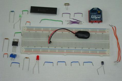
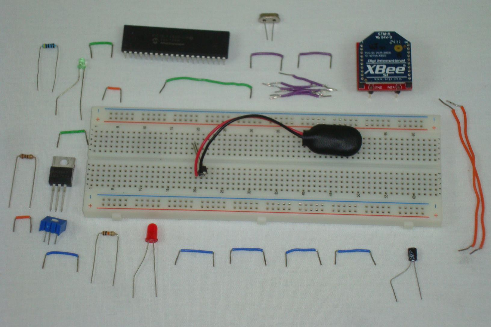
First we'll start out with all of the parts on the table, ready to be assembled. Make sure you have all the parts like I do and then get started building!
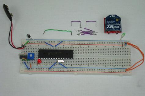
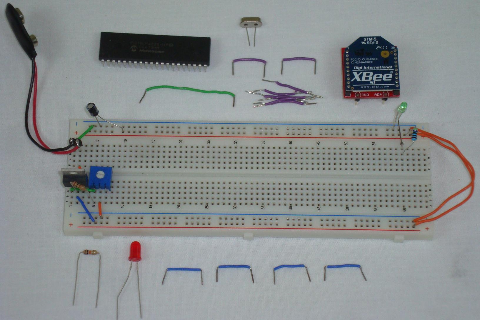
·The LM317 +3.3v circuit is assembled first. The trimpot will let you vary the output voltage to hit +3.3v.

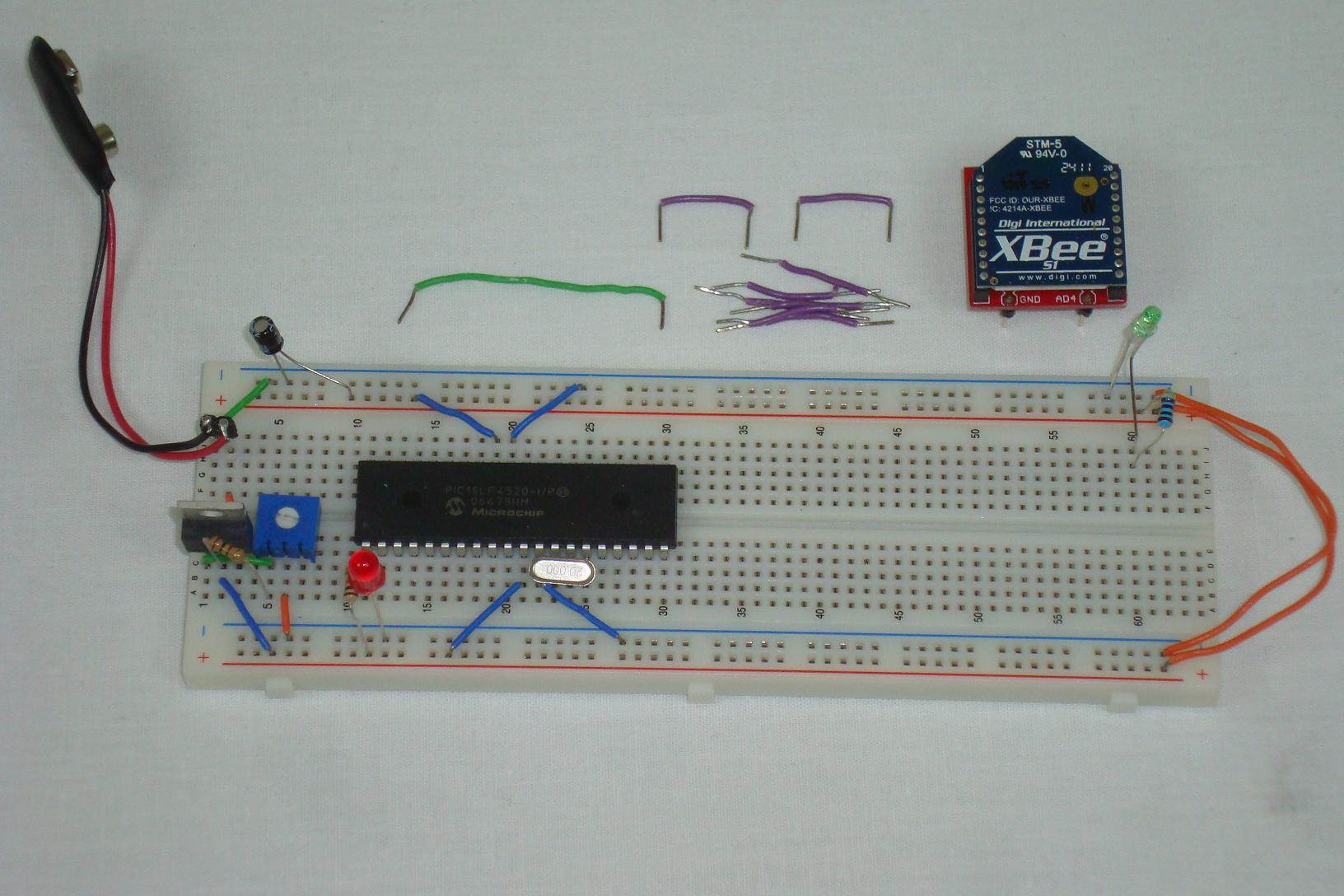
·The standard 'minimal' PIC circuit is assembled and connected to power/ground.
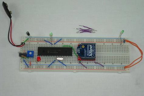
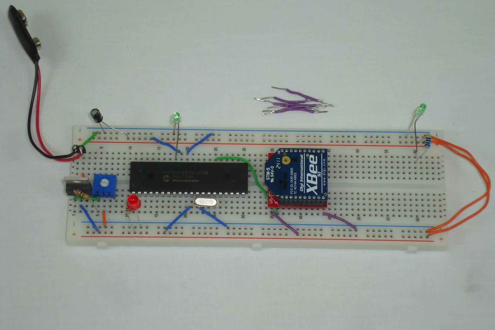
·The XBee module is added to the circuit, connected to power, ground and the serial data input to the PIC.
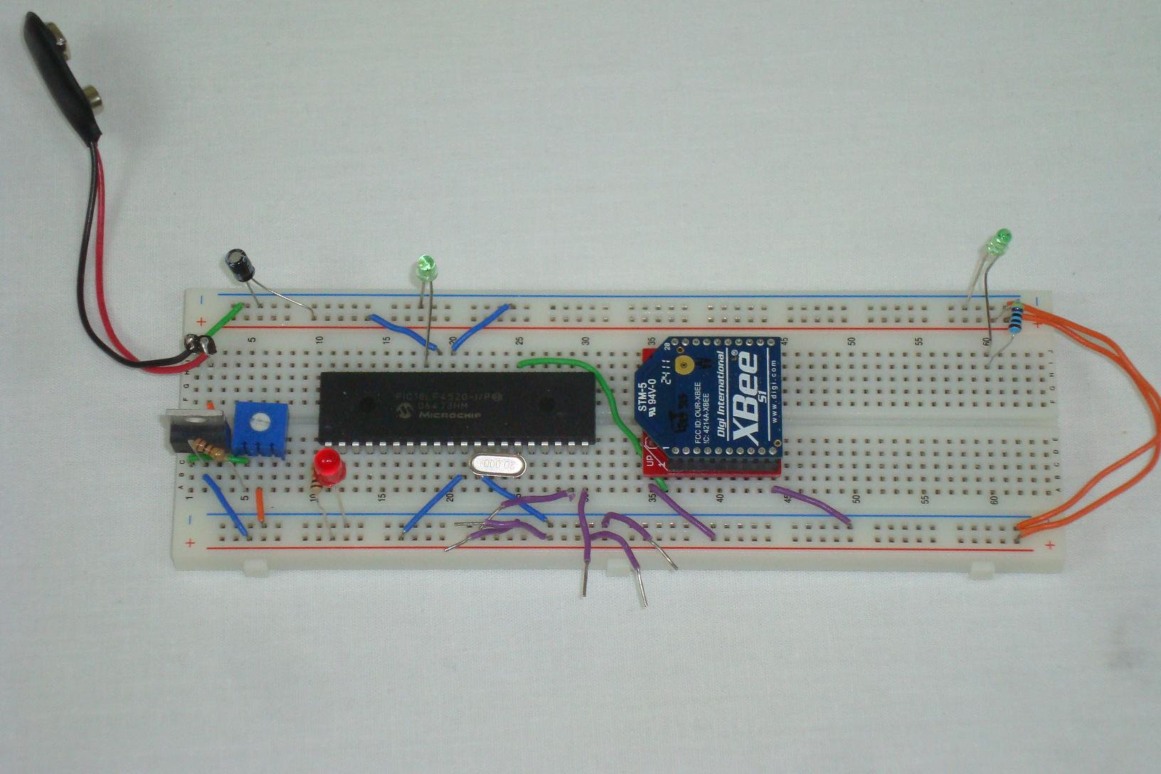
·6 wires are added to connect the servo to the system's power, ground and PIC ouput.
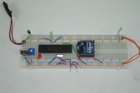
·The two servos of the tilt/pan mechanical system are connected to those 6 wires.
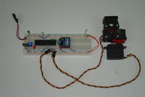
·That's it! The receiver system is wired up and ready to be programmed with some software.
In this second half of the hardware section, we will follow the schematic for the receiver part of this project and build the assembly. There aren't too many parts so it shouldn't take too long. This guide assumes you already have the mechanical tilt/pan system assembled.
Building The Circuit
First we'll start out with all of the parts on the table, ready to be assembled. Make sure you have all the parts like I do and then get started building!
·The LM317 +3.3v circuit is assembled first. The trimpot will let you vary the output voltage to hit +3.3v.
·The standard 'minimal' PIC circuit is assembled and connected to power/ground.
·The XBee module is added to the circuit, connected to power, ground and the serial data input to the PIC.
·6 wires are added to connect the servo to the system's power, ground and PIC ouput.
·The two servos of the tilt/pan mechanical system are connected to those 6 wires.
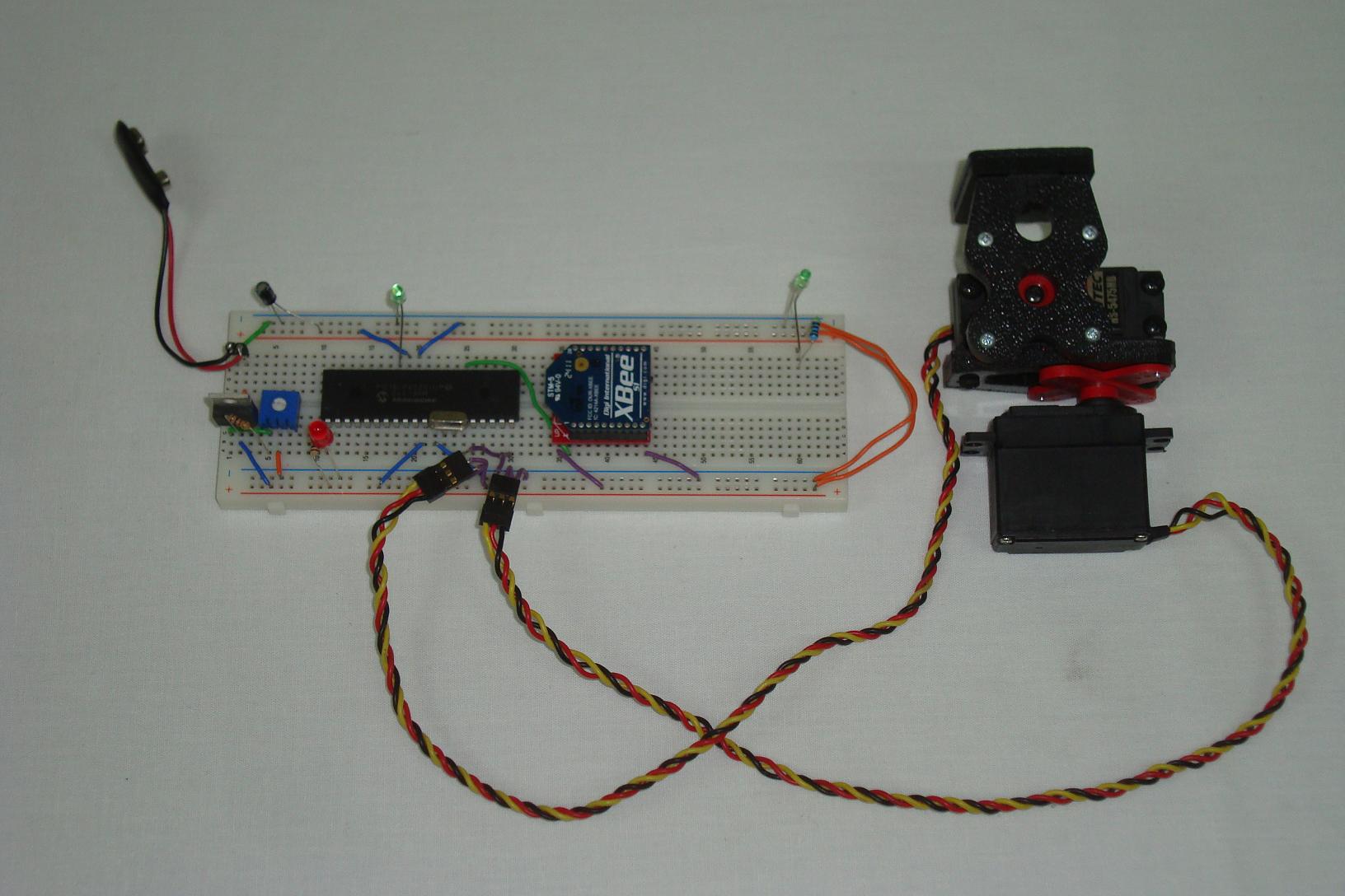
·That's it! The receiver system is wired up and ready to be programmed with some software.