Schematic Overview
There are two schematics for this project, one for the transmitter and one for the receiver. The transmitter is fairly simple, and the receiver is a little more complicated. The main parts in the schematic are the PIC 18LF4520, XBee Modules and HS-485 Servos.
Cadsoft Eagle Project Files: Wireless XBee Pan/Tilt System
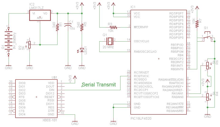
Transmitter Schematic
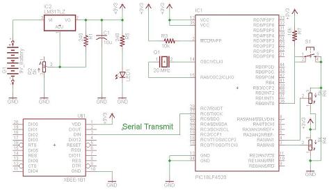
View Full Schematic
Trimpot Input Into The PIC
The input we will give to the PIC's will come from two standard trimpot outputs. The trimpot is tied to power and ground, with the middle pin being a variable voltage send to the PIC's A/D converter on pin RA0. A second trimpot is connected exactly the same and enters the PIC's second A/D converter on pin RA1.
Xbee Module Wireless Output
The PIC will then translate this input to an integer of value 0-7 and send it via the PIC's serial communication module at 9600 BPS to the Xbee's Din pin.
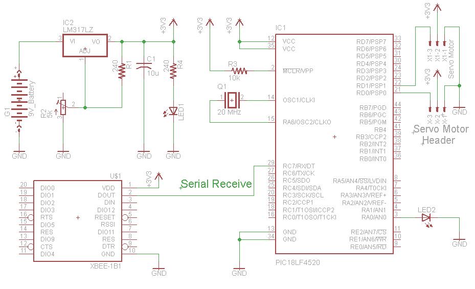
Receiver Schematic
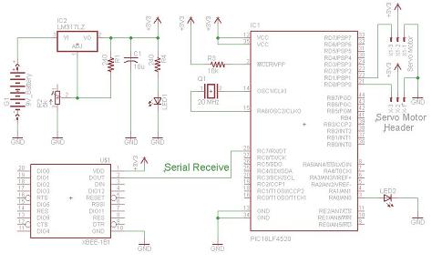
View Full Schematic
Servo Motor Output
After the serial data is receieved by the PIC for each servo channel, it decodes the 3 bits for tilt servo angle, 3 bits for determining pan servo angle and 1 bit for the LED switching proof of concept.
Xbee Module Wireless Input
The Xbee receiver will automatically connect with the transmitter and begin receiving data. All data will be receiving and output via the Dout pin on the Xbee module. The Dout pin is conneceted directly to the PIC's Rx pin so that the PIC can catch the data.
There are two schematics for this project, one for the transmitter and one for the receiver. The transmitter is fairly simple, and the receiver is a little more complicated. The main parts in the schematic are the PIC 18LF4520, XBee Modules and HS-485 Servos.
Transmitter Schematic
View Full Schematic
Trimpot Input Into The PIC
The input we will give to the PIC's will come from two standard trimpot outputs. The trimpot is tied to power and ground, with the middle pin being a variable voltage send to the PIC's A/D converter on pin RA0. A second trimpot is connected exactly the same and enters the PIC's second A/D converter on pin RA1.
Xbee Module Wireless Output
The PIC will then translate this input to an integer of value 0-7 and send it via the PIC's serial communication module at 9600 BPS to the Xbee's Din pin.
Receiver Schematic
View Full Schematic
Servo Motor Output
After the serial data is receieved by the PIC for each servo channel, it decodes the 3 bits for tilt servo angle, 3 bits for determining pan servo angle and 1 bit for the LED switching proof of concept.
Xbee Module Wireless Input
The Xbee receiver will automatically connect with the transmitter and begin receiving data. All data will be receiving and output via the Dout pin on the Xbee module. The Dout pin is conneceted directly to the PIC's Rx pin so that the PIC can catch the data.