Schematic Overview
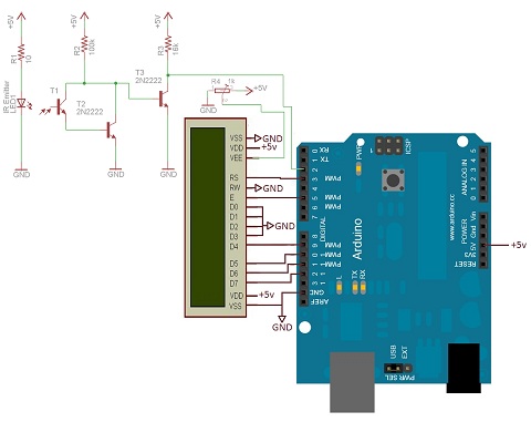
The circuit diagram for this project is a little more complicated than last week's 16x2 LCD Interface. For starters, the LCD interface is simplified to have only 2 control lines and 4 data lines. Then the tachometer IR break-beam circuit is added on the side to make things a little more complex.
View Full Schematic
Schematic Specifics
16x2 LCD Interface
2 control pins and 4 data pins are connected from the Arduino to the LCD. These are what will tell the LCD what to do and when.
IR Break-Beam Circuit
The break-beam circuit's signal goes to the digital input pin #2 on the Arduino. This will interrupt the Arduino so it can count that a pulse has just been registered and the tachometer is reading data.
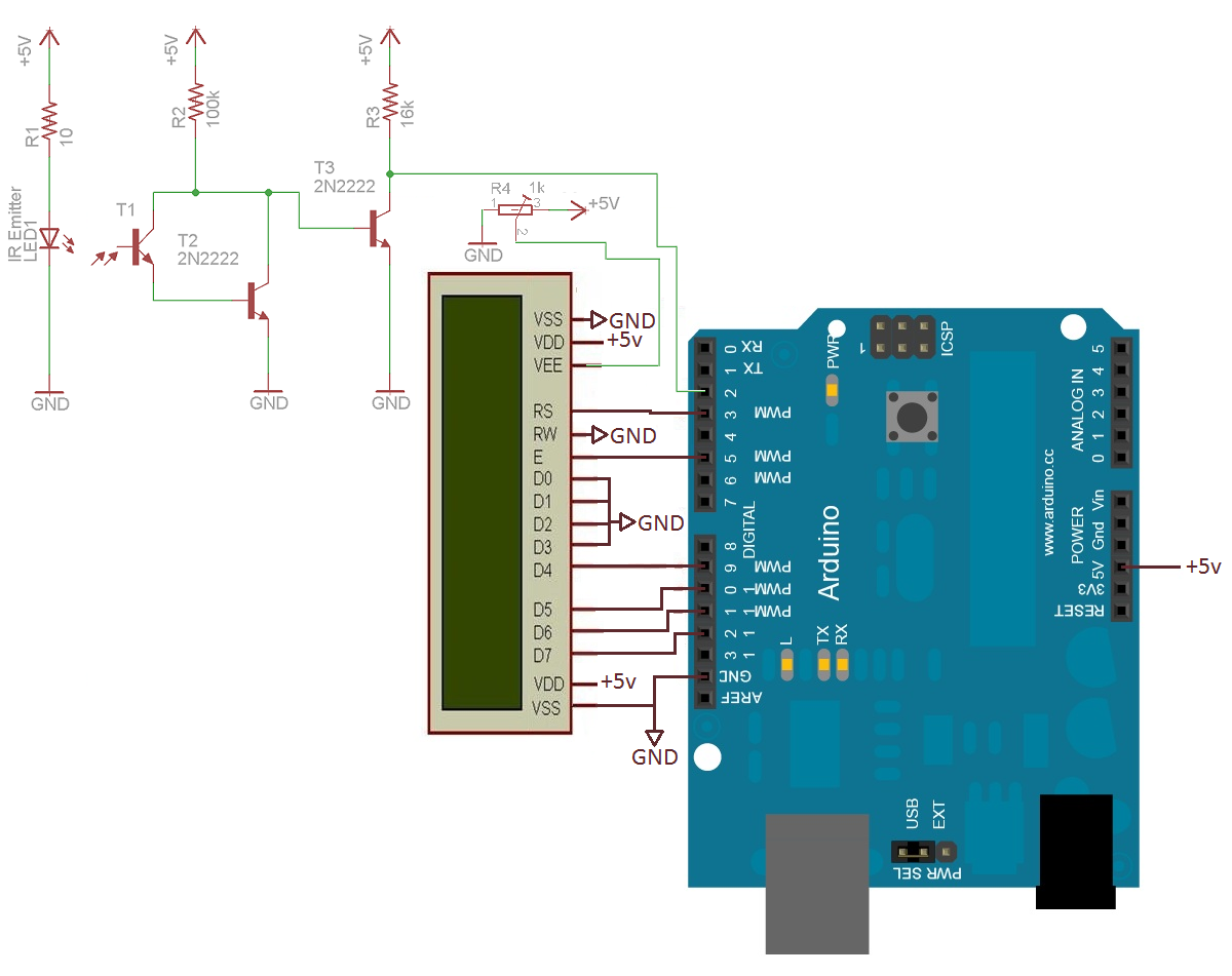