Hardware Design
There are two main portions of the hardware design here. The first is connecting the LCD to the Arduino like we did in the 16x2 LCD Arduino Interface. The second is building the IR break-beam circuit. Still there's not too many parts, so it shouldn't take very long to build.
Building The Complex Circuit
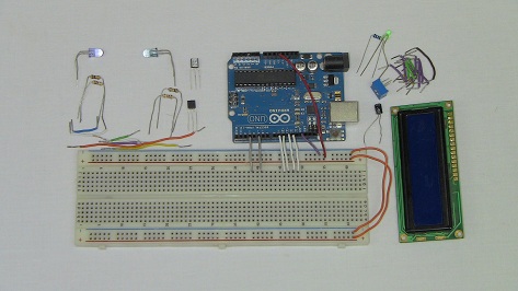
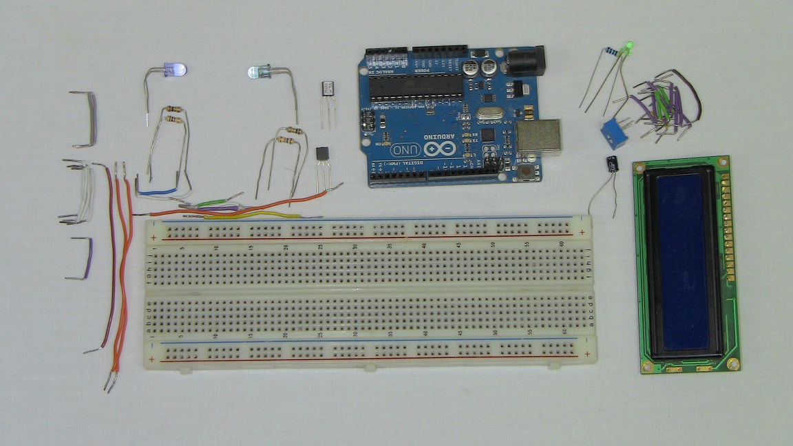
Below you can see all the parts necessary to get started wiring the circuit up exactly as you saw in the schematic details.

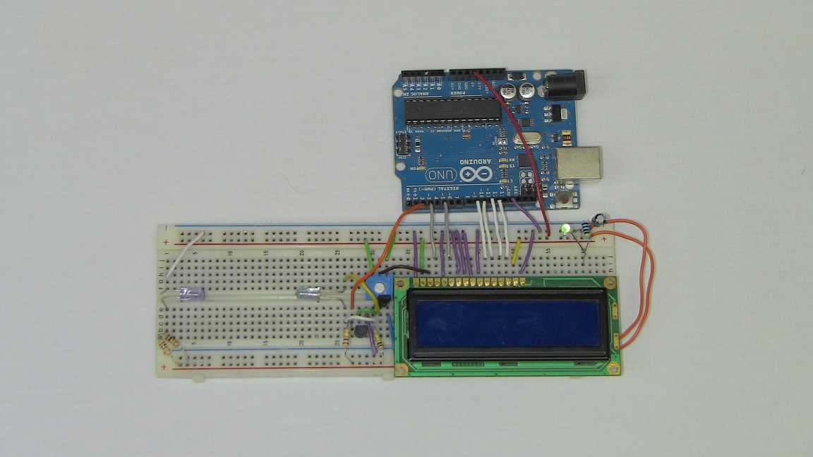
·First the +5v power and LCD data/control connections are made.
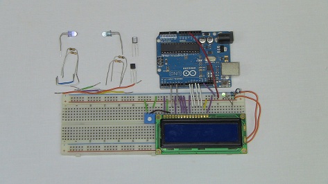
·The LED is connected, along with contrast control and power LED.
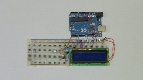
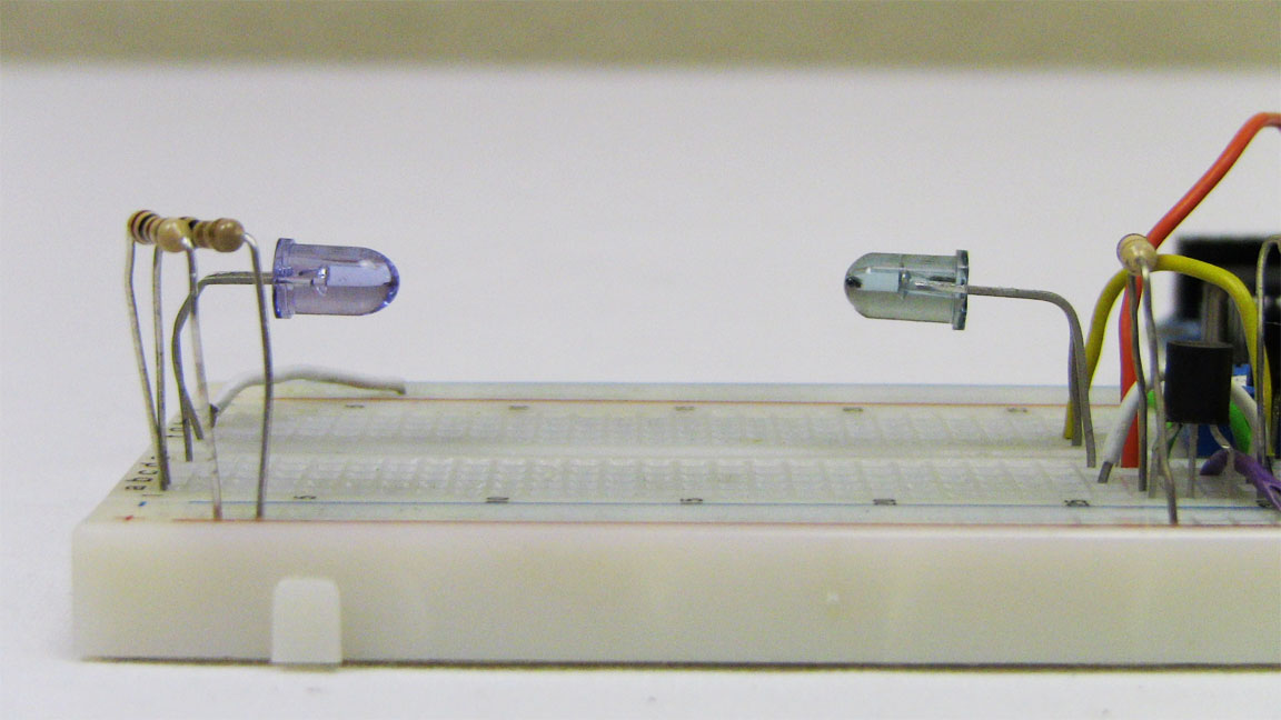
·The IR break beam circuit is now assembled. Try to keep a good distance between the IR LED and phototransistor.
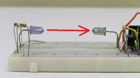
·Here you can see a decent distance between the IR transmitter/receiver, where I'll put the CPU Fan.
·Enough hardware talk! Let's get started with some firmware/software so we can see this thing in action.
There are two main portions of the hardware design here. The first is connecting the LCD to the Arduino like we did in the 16x2 LCD Arduino Interface. The second is building the IR break-beam circuit. Still there's not too many parts, so it shouldn't take very long to build.
Building The Complex Circuit
Below you can see all the parts necessary to get started wiring the circuit up exactly as you saw in the schematic details.
·First the +5v power and LCD data/control connections are made.

·The LED is connected, along with contrast control and power LED.

·The IR break beam circuit is now assembled. Try to keep a good distance between the IR LED and phototransistor.
·Here you can see a decent distance between the IR transmitter/receiver, where I'll put the CPU Fan.
·Enough hardware talk! Let's get started with some firmware/software so we can see this thing in action.